PIETECH Manual: There has been a “Manual” in the works for a while now. It is coming together well and once it is completed it should be a valuable resource for anyone wanting to experiment with Inertial Propulsion without spending untold hours with trial and error testing and expensive components that may not be exactly what is necessary. I have several reasonably complete drafts sent out to other people familiar with this technology for their opinions and criticism. Below is a preview shot of the Cover and the Table of Contents as it is right now.
I am hoping to have this available before the end of the year!
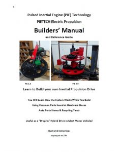 |
| PIETECH Manual Cover |
There is also a section within the manual that explains the mechanisms which create the driving force in greater detail than has ever been published, to the best of my knowledge. Color photos and detailed instructions means that little or no math is necessary to follow along, build a working PIE 1.0 or 2.0, and gain a better understanding of the inertial propulsion principals proven to work via the PIE.
Continuing on with the PIE 4.3: Now I am preparing to expand the PIE 4.3 into a 2-wheeled unit running in the 200 to 300 RPM range. Tests have proven the possibility of running RPMs in the 850 to 1000 range, but the components would need a pretty severe redesign in order to sustain those RPMs for more than a minute or two, so I am planning on staying under 500 RPMs for now.
Component Failure: The damage from running at full speed (around 875 RPM) is significant. Both outer stops were broken (twice each), and the sprocket gears used as the planet gears have many bent teeth.
Much of that damage was incurred when the outer stop(s) broke and the weight could jam the assembly. That is also when timing would jump.
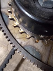 |
| “Overspeed” Gear Damage |
Possible Gear Changes: Notably the sun gear is completely undamaged! Since there is no damage there and considering the severe pounding the gears in the PIE 2.0 suffered with only minor issues (spot welds breaking), I am reluctant to purchase expensive spur gears which will absolutely have weaker teeth than my homemade ones. Better welding, and perhaps a coating should make perfectly acceptable gears that will stand the abuse of slinging the PIE’s weights.
Sprockets for Now: I will probably continue to use the sprockets as planet gears for now, but if they continue having damage issues they will need improvements to minimize the problem.
The sprockets I am using in the PIE 4.3, they are 40A26 sprockets with a 1” center hole. When I weld in the rods, I could skip every other space and that would make 13 tooth gears that would be much stronger and mesh with better precision than just welding rods to a flat pulley.
Those sprockets are very inexpensive from https://www.surpluscenter.com (around $3 US each at this time) and they are easily welded.
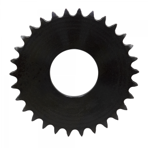 |
| 40A26 Hubless Sprocket |
Adding to the PIE 4.3: I now know for a fact that the PIE 4.3 produces 20 oz. of thrust at 275 RPMs, and it runs smoothly at that speed. A second wheel is being added, and it will need to be timed to the first wheel, so a chain drive is being planned out for the drive. I would ideally be able to test with both synchronized “sympathetic” spin wheels and also test with synchronized but “opposing” spin wheels and switch directions as easily as rerouting the chain and having a second set of weights. Time will tell how that works out.
Wheel Configuration: It is VERY tempting to stack the wheels up for this higher speed unit, like the PIE 2.0, but I think it should be a side-by-side to make the switching of directions as simple as possible. I suppose the question should be regarding the placement of the second wheel. Beside the 1st one or in front of it? Perhaps that is something else that should be “changeable” for experimentation purposes as well…
MORE TO COME SOON
