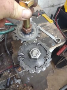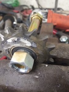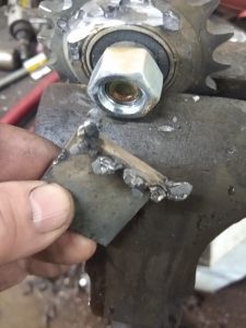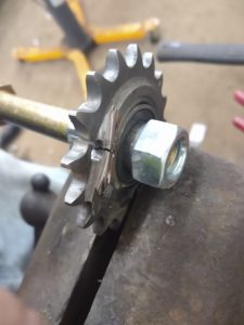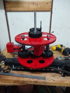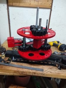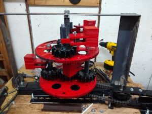
Next Gen Test Gear |
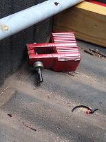
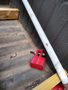
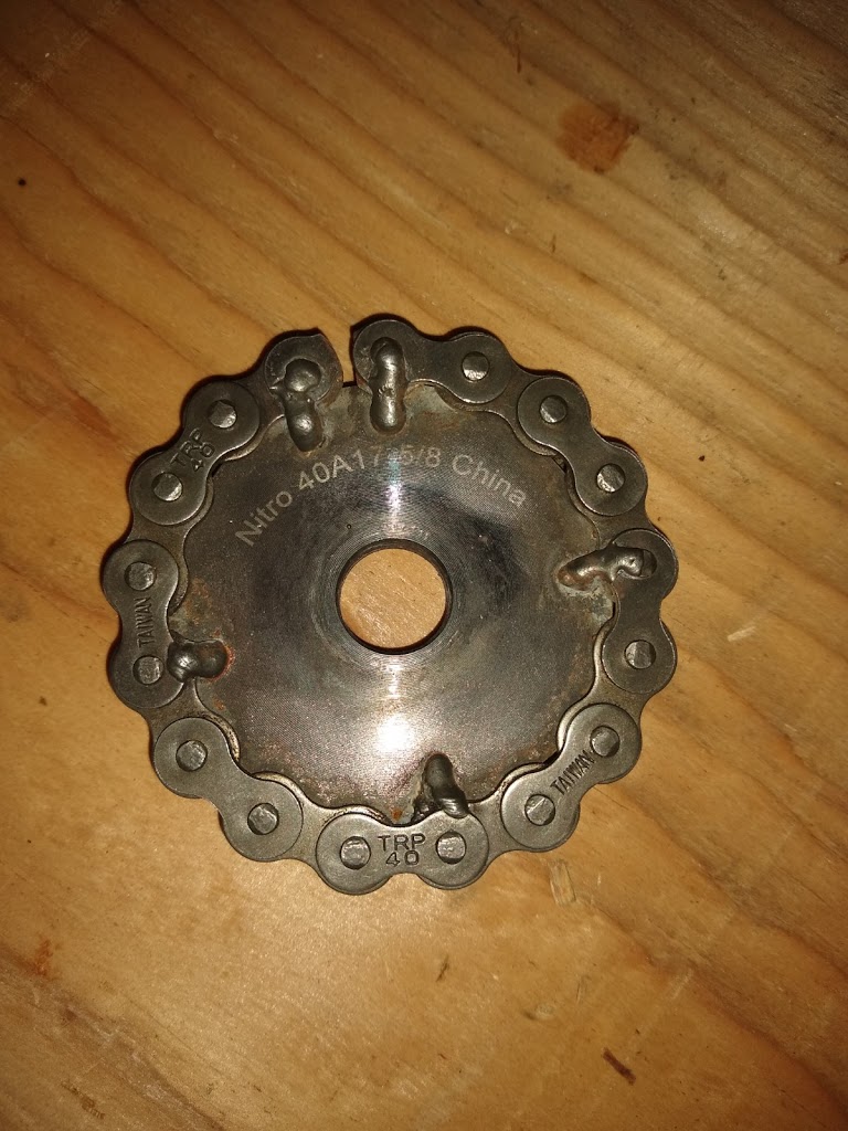
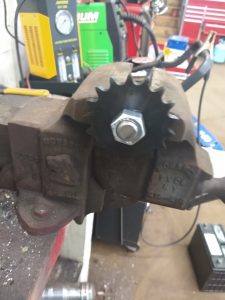
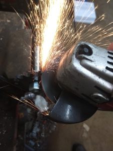
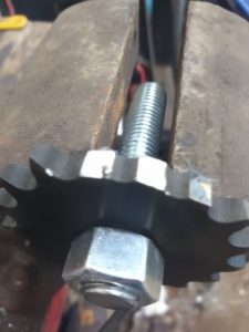
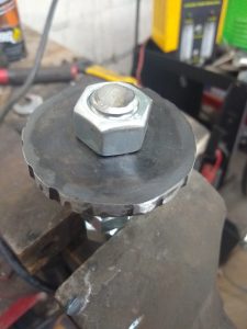
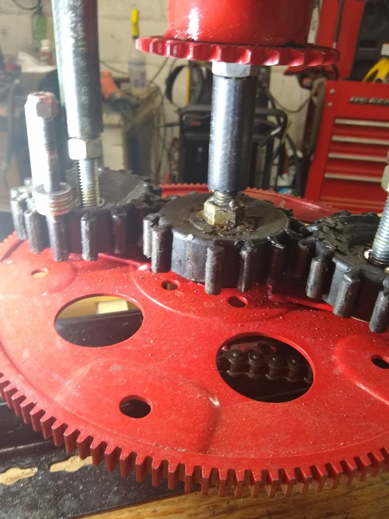
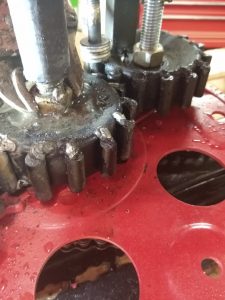
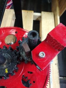
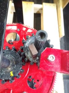
Welds Popped Off |
Welds Still Have Sprocket Metal On Them |
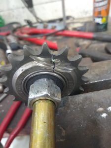
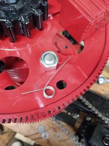
Ground Flat and Drilled – Cracked When Tightening Bolt |
Inertial Propulsion
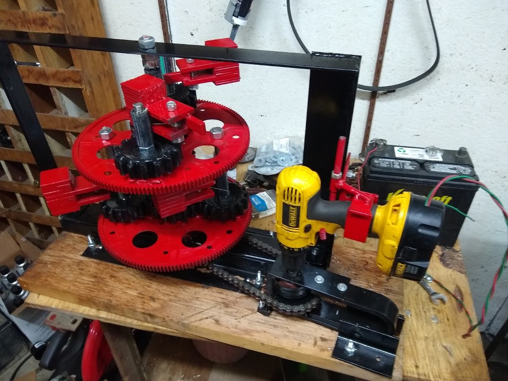
Next Gen Test Gear |
Welds Popped Off |
Welds Still Have Sprocket Metal On Them |
Ground Flat and Drilled – Cracked When Tightening Bolt |
The PIE 2.0 is running much better now, and although it was not without frustration, I was finally able to make some test runs.
I did have to make some repairs to the lower sun gear and I also corrected the crooked outer stop. One of the teeth on the lower sun gear broke off and when that happened the lower wheel started “jumping timing” like crazy.
When the failure(s) happened, the timing got pushed to the 11 o’clock position and that is a bit too “retarded” or “late”, the planetary alignment position (I like that terminology) should be a bit earlier at about 10 o’clock. This late timing is very evident in the PIE’s upper framework, when running at just over 100 RPMs the upper frame deflects to the right which tells me I am losing forward propulsion power.
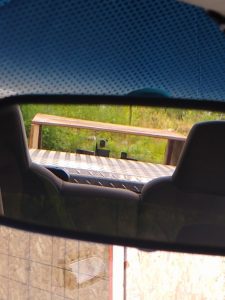
I am fortunate enough to be able to see the upper part of the pie in my rear view mirror while driving so I was able to visually see that the timing was off.
I took a short video of the sideways movement to demonstrate this to anyone building a PIE, I will show it here but I probably won’t post it on YouTube or Bitchute since it falls under the heading of a builder’s note but here it is.
During testing, I did not have the tools with me to adjust the timing (won’t make that mistake again – I hope) so the results listed below were obtained with incorrect timing.
Testing:
To eliminate variations in atmospheric and fuel conditions, all comparative tests are run consecutively.
Test Track: 1.2 miles with a 20-mph speed limit (during business hours) around a nearly abandoned shopping mall with 2 stop signs.
The Scanner used to collect the data is a Matco Determinator, which is the Matco branded OTC Pegisys scan tool system, and the test vehicle is a 2005 Chevrolet Colorado Z85 crew cab pick up truck with a 3.5 liter engine and automatic transmission.
Multiple passes were made both with and without assistance while monitoring vehicle speed and engine load on graphing scales with a running average counter. There were some anomalous results obtained that showed both better and worse results, so they were “thrown out” and only the repeatable results were used to obtain that which is shown below.
Average speed measurement during all test runs was maintained at 17 to 18 mph.
Engine load average without PIE assist. – 40%
Engine load average with PIE assist. – 36%
Total gain with PIE 2.0 was a 4% reduction in engine load. This “should” improve with the timing correction; results will be posted here and on MeWe.
Well it works, but as with any new design there are issues. I have put around 19 miles on it and it really does seem to work well, when it will keep running.
First and foremost is the locking up problem. The little springs did a reasonably good job of stopping the lockup on start-up, unless I started it at a bit of a higher speed. High speed start-up would overpower the springs and locking was still an issue. Then came the locking problem while driving. Every time I might hit a bump, or tap the brakes, it would lock up. So, I took the weights off, cut the metal tab off for the outer stops, and welded stops onto the planet gears. One corner of each weight then had to be trimmed so it would not hit the new stops and viola, no more locking. I did get one of the stops a bit crooked, but I will fix that next week.
Second was the drill motor kept cutting out. Apparently, there is a bad spot in the variable speed trigger, and (of course) I found it. With the new stops came a bit of a smoother run at higher speeds, so I upped the speed and the motor no longer stopped randomly… Until the fuse blew… Replaced fuse with circuit breaker and then the chuck loosened up on the chain drive shaft…
The PIE did lock up one more time, because of the crooked outer stop (that I WILL be fixing next week) the weight hit it hard enough to slip past it and lock on the back side. Reset and speed reduced slightly it seems to have worked fine on the last trip around the block, although there is a definite speed to power correlation. More speed=more power!
Once testing on this model is complete, a high-speed unit is definitely on the drawing board!
I do have to wonder why… Why it is that when testing on public streets and roads it seems that every bad driver within miles is attracted to the test vehicle?!?!? Getting tailgated, cut-off, swerved at, nearly t-boned, and behind extremely slow drivers happens every time. I sure am glad it’s Friday!!!
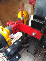
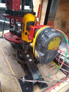
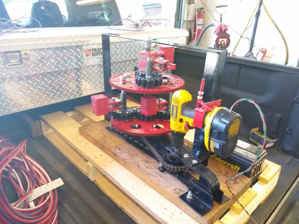
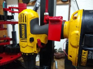
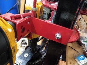
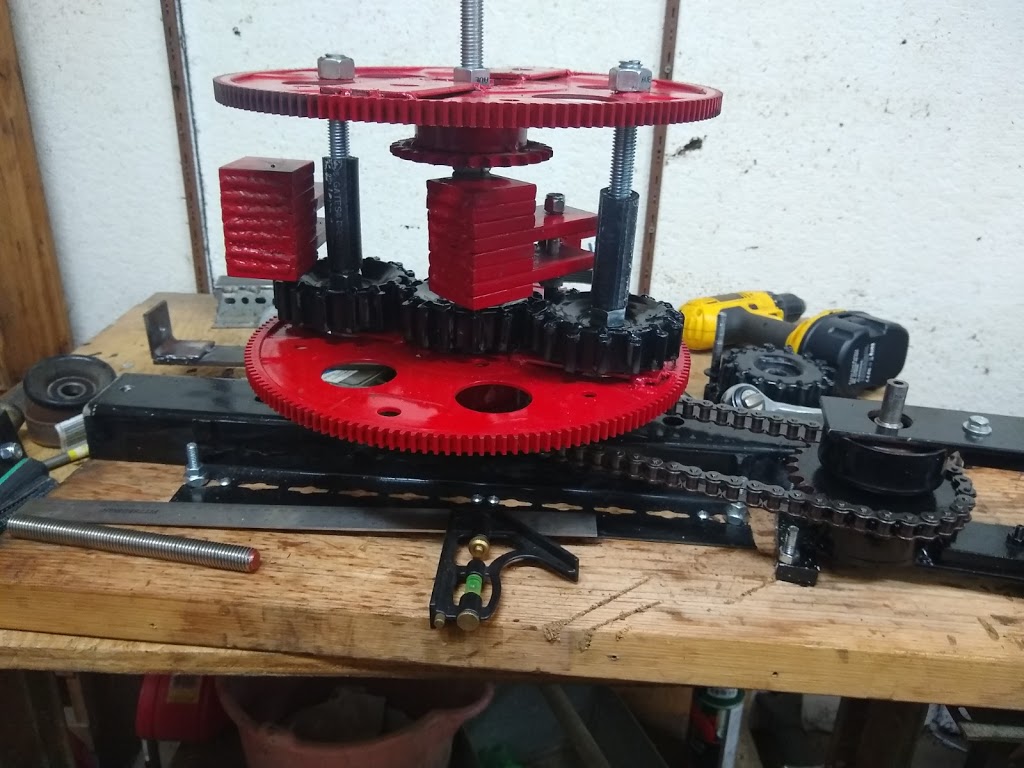
The PIE 2.0 is basically ready for real world testing. The PIE is fastened to a pallet and is being driven by the cordless drill used to test it. I made a bracket for the drill and “gutted” an inoperative battery pack so I could connect wires easily. This allows me to power it from the vehicle’s electrical system or a 12V battery so that a simple on/off control is accessible to the driver.
PIE 2.0 Ready to come off Work Bench |
The Power for the PIE 2.0, and the Bracket for the Drill
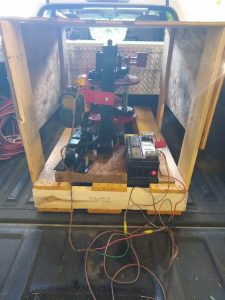
I do still need a weather cover as it will be tested in the same pickup truck as the PIE 1.0 was, but that is the simple part of the whole project.
I will be posting all findings here on the blog and also on MeWe (www.mewe.com/i/bryanstclair).
I want to reaffirm the intent of the Grassroots Mechanic Movement (GMM) to freely distribute and promote the “reactionless” propulsion technology of the Pulsed Inertial Engine (PIE). I do not advertise the Grassroots Mechanic Movement, and I do not charge anything for the full disclosure information published either here or on the blog. I also do not have any monetization (at this time) of my videos or the blog. The videos are available on YouTube as well as Bitchute and I find it rather interesting that there are a lot more views on Bitchute.
I encourage mechanics, tinkerers, technicians, and anyone who is curious to build one of these and PLEASE post the results.
Too many people who made public statements and videos about this tech claimed it was not workable, but they also did not follow ALL of the original instructions laid out by the original inventor, Brandson “Roy” Thornson. The important internal “trigger” mechanisms were not built and installed, so the “replications” weren’t really replicas at all.
Check my videos, actually read my blog, download the shared files listed within the blog, visit MeWe, and then go to your workshop and build one for yourself. I have laid out the build to be as inexpensive as possible utilizing many used parts from the auto recycling yards, scrap metal pieces and even custom building the gears without a machine shop.
In less than 1 weekend of puttering around the garage (like many of us do) any hobbyist, or home mechanic, with a grinder and a welder can have a single wheel with 1 weight working and proving that this technology works.
Building Upward & Using Torsion Springs
I have repeatedly said that I would make this project 100% open source, I am keeping my word and even though I don’t have it ready to run yet, I am posting a reasonably major update now.
I have not posted any real updates as to the status of the PIE 2.0 build in the last few days, so here is what I’m up to.
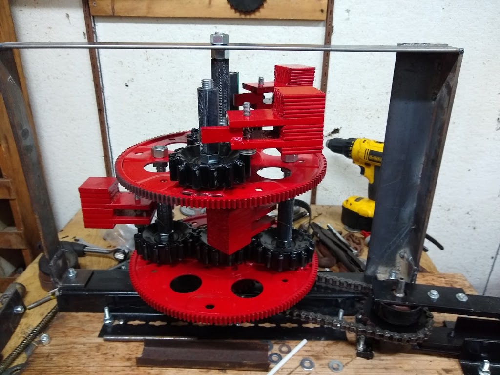
The PIE 2.0 is progressing very well so far. I had a problem with the weights “jamming” on start up because I am using the planet gear axles as the outer stops. This seems to be alleviated by using very weak torsion springs to push the weights out of the position that jams the rotation. The springs add very little to the force of the weights swinging outward and should pose no significant change to operation. I will include more info about the springs if anyone requests it, and if there is someone following this who is also building a PIE 2.0, I can get these springs for you if you let me know.
This significant change is an integral part of the now modular nature of the PIE 2.0 and “should” be a design that can be expanded in time. It also gives the PIE 2.0 a much smaller footprint, this will allow it to be installed and used effectively in much more confined areas.
This modular design could also be further developed with a logic controller and individual stepper motors controlling each wheel. That would allow non-linear build designs that can be suited to custom applications.
With this new “double-decker” design, I am also enhancing the framework so that (hopefully) testing can be completed without the unit breaking itself too badly under load. Remember that this is still a prototype and prototypes are built to reveal flaws and weaknesses as well as being a testable model.
Bench Testing
It is easy to see the rpm variation potential now that slip is eliminated between the drill and the PIE’s wheel. For testing purposes, I have braced the drill with a piece of metal so it wouldn’t keep pulling it back and causing speed variations since I was not holding it steady enough.
As I continue the build, I still have not decided on a motor to power it. I do not want to commit to any particular motor design or speed, before doing some initial testing. There is still more work to do before I get to that point, at which time I will post those results here as well.
I am certain of is that if the PIE 2.0 becomes much more powerful, the whole unit will need a redesign so that it does not tear itself apart!!
I am also considering installing some very light weight springs to keep the weights from folding inward when it is not running. When that happens, the assembly can jam and not turn, it is as close to a “backfire” as the PIE 2.0 can have. The springs need to weak enough not to affect operation, but strong enough to do the job. I made it work with rubber bands, but they certainly won’t last long. It is something to think about.
Addendum 6/11/2020: As I was thinking about the possibility of adding some sort of spring (rubber bands work well) I noticed a spring clamp in my toolbox. EUREKA!! That is most likely the answer, a torsion spring! Like a mouse trap spring, the torsion type spring might be exactly what I need to keep it from “stalling on startup” without applying enough force to change how the PIE 2.0 works!!!
Bench Testing Chain Drive with Drill as Power Source
I finally got my sprockets for the chain drive! They are surplus so there are nicks and dings, but nothing a file won’t easily fix. They have an “unfinished” one-inch (25 mm) hole, that puts the hole slightly undersized, but that actually worked out in my favor for use on the jack shaft as it made for a nice press fit on the 1” section of shaft. I then welded the sprocket into place on the shaft to make it a permanent install.
I used a plasma cutter to open the 1” holes up on the sprockets being used on the wheels, that way there is no need for spacers to mount them on the axles. Cutting the hole open like that is ugly, but I don’t really care, as it cannot be seen once it is installed.
I put it together enough to see the chain drive work with a cordless drill running it up to approximately 1500 RPMs. I still need the parts bolted to the plank base so that nothing can shift position with the weights installed.
I believe that I will wait to finish the drive assembly with a motor until I can see how much power it is going to take to make it run, and at what RPM. I have several large electric drills that I can use to do those tests if necessary.
Truing a Sprocket on a Wheel Assembly, Getting Ready to Weld
Bench Testing Chain Drive with Drill as Power Source
Dual Weight PIE Bench Test & Making the Drive Jackshaft
Two days ago, as I was finishing up for the day, I decided to put both new weights on a single flexplate assembly at the same time. I really did this as a way to see the action and make observations of any interference between them. I was pleasantly surprised when the interaction appeared to be complimentary in nature.
I was so pleased with the interaction that I decided to “spin” it up with the cordless drill. The amount of power being transmitted to the bench was remarkable, and because the flexplate was “balanced” out with the second planet assembly, I was able to run it at a somewhat higher speed without further modification.
I observed the weights each contacting a stop (one inner, one outer) at virtually the same time and producing complimentary pulses. I was so pleased that I immediately cobbled together a way to hold my phone and video this (the video is below and on YouTube).
Powered Dual Weight Bench Test
Now I am getting ready to put the chain drive on it, although I am no longer sure it is necessary to have a positive non-slip drive. I am including some pictures of the jackshaft being made at a local home-garage machine shop. I didn’t have any keyways cut into it, but I can always take it back for that if necessary. The dimensions are ½” up to 17mm up to 1” and back down to 17mm.
Cost was negligible for this because I supplied the metal to a home machine shop (along with beer) on a Saturday. Normal cost for this at a local machine shop would have been around 35 to 45 USD according to a couple of calls made, but many machinists would do this on their lunch hour at work for about $20.
Jackshaft in Lathe & Finished
The plan is to weld a sprocket onto the 1” diameter section of the shaft, then bearings will be mounted on the 17mm sections and then the ½” diameter end will be used for the electric motor’s connection.
According to the surplus company I ordered the sprockets from, I should have them in about 3 days…
Newest Weight Ready for Testing |
Building the revised PIE, version 2.0, is well under way. There are two weights are virtually ready for testing. The gears are looking as good as they ever will, and the base has been partially modified to accommodate the revisions in the configuration.
I have decided that the drive system will be using #40 roller chain & sprockets. The sprockets and chain are available at a very reasonable price from surplussupply.com. It is too bad that they do not have spur gears to use for the sun & planet gears as well. Regardless, I am getting as much done as feasible while I wait for the sprockets arrive (I already have chain).
A custom shaft would be unnecessary if the shaft, sprocket and available bearings were all the same diameter, but weighing the option of sourcing more components vs. those already obtained and having one custom component made I choose the latter. A local machine shop would make the shaft for between $25 and $50 US, while pillow block bearings would be that price for each one. As previously stated, the objective is a simple, replicable drive, that is also safe and affordable.
Testing the Action of the Second New Weight
First:
The PIE 2.0 project has commenced. As could be seen in the pictures contained in my last post, a new weight is being developed for PIE 2.0. I plan on using the same design for the planetary gear sets because I they are simple and robust. I was not sure about the flexplates, but since they are already prepared for the purpose, I will use them until a reason to change presents itself. Some parts are being reused (from the 4-wheel unit) and/or repurposed. There are still many questions to be answered and most of them need to be put on the work bench in order to find the answer.
We know that computer models and all the advanced trigonometric formulas in the world are useless unless there is a way to put them to work. The differences between types of drives can be discussed, compared & argued but the proof is in the workshop. Sooooooo… I need to make something PERFECTLY clear.
The fact is, this damn thing works!
Setting up for bench Testing |
Second:
The Problem with Physics is that Some Science is Not Allowed:
Science is: The observation, identification, description, experimental investigation, and theoretical explanation of phenomena.
Physics is: The science of matter and energy and of interactions between the two.
Our currently taught physics does not allow for certain outcomes, and any drive system that does not push against anything for propulsion is one of those outcomes not being allowed for.
Along with physics departments worldwide, NASA currently discounts this type of tech as fantasy. Yet NASA is currently using reactionless propulsion to position/reposition satellites in Earth’s orbit.
Countless scientists have witnessed a very early version of this system operate with greater efficiency than wheel driven, jet, propeller, or rocket driven forms of propulsion, yet they turn right around and state unequivocally that it is impossible and absolutely cannot work…Ever!
Many witnesses will deny that they ever saw, or that there ever was, a working demo.
People’s lives have been ruined because they built a working device and tried to sell it to big business and/or governments.
Science teachers worldwide are told that if they teach this as a possibility, they will be fired. The only way this can be included in a curriculum is by “proving” it doesn’t work.
It seems that the ONLY ALLOWABLE outcome has been negative or no.
Since this Grassroots project flies in the face of all of that, I continue to publish ALL information regarding the PIE system (1.0, 2.0 and future versions) and as stated earlier, the inconvenient fact is that this damn thing works!
I hesitate to say that I am working to change the paradigm, but it works and it is repeatable.
This knowledge NEEDS to go public, needs to be peer reviewed, and needs to be put to use helping people everywhere travel more efficiently.
PIE 2.0 To-Do List (Subject to Change of Course):
1- Set up outer stops for the new pendulum weights
2- Enhance bearings on all rotating assemblies (Doubles?)
3- Strengthen framework to withstand higher power output
4- Higher speed & strength motor
5- Synchronous drive system (Roller chain, T-belt?)
6- Consider “stacking” flexplates rather than side-by-side positioning to reduce footprint
7- Consider sourcing off-the-shelf parts for future versions, kits, etc.
A personal note:
As I am writing this, I want to thank everyone for watching my videos and reading my words.
I need to remind everyone following along that I am funding this completely out of my own pocket and then sharing it freely. I am not accepting donations nor am I selling anything for funding or profit.
There may be a saleable product in the future, however, ALL of the info in my personal journal & subsequent public blog are still going to be free as long as I have a say.
Perhaps, eventually, kits might be made available. I can imagine a kit to add hybrid capability to a vehicle for about the price of a go-kart.
Right now, I want to share this with everyone, worldwide. I would hope others would see how simple this is to build a PIE as well.