PIE 4.8 – The APEC 5/1/2021 Conference and the “Inertial Doppler Effect”

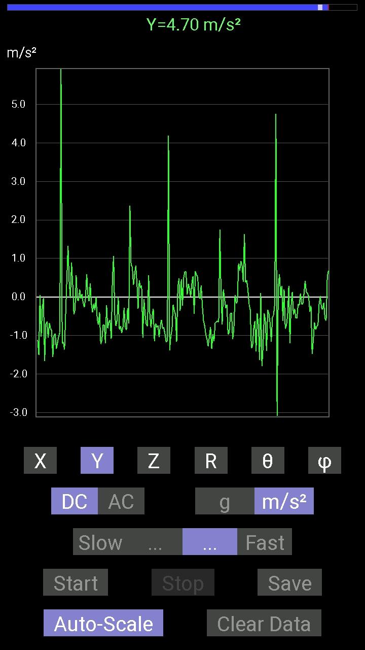
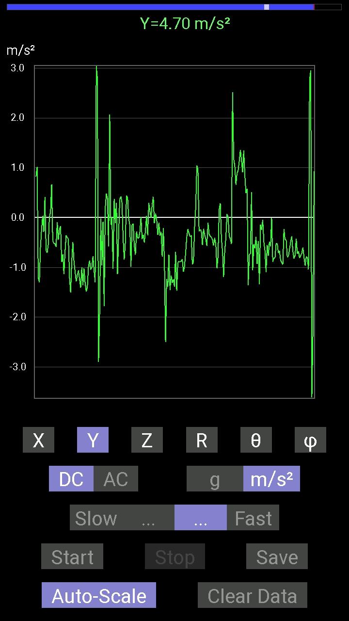
The PIE 4.8 CCW wheel is pretty well set. I have attempted to get some force tests done with a force meter, the output readings were very unstable at best. I was however able to get some slightly better readings with an accelerometer.

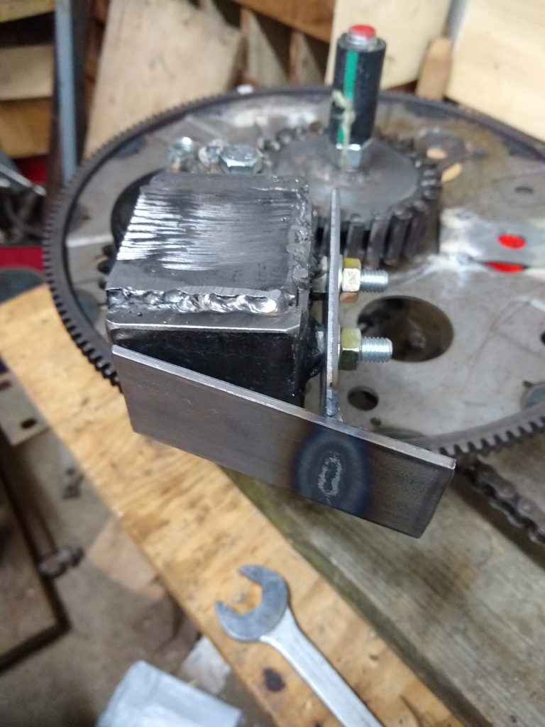
The photos are screenshots from an accelerometer app on an android phone. The waveform or trace is below the “0” when pulling forward. It is obvious that there is a more stable pull during each pulse forward, and disorganized spikes in the reversion direction. Keep in mind that it will show a small reverse pull between forward pulses just because the chassis slows slightly between propulsive pulses.

On Saturday 5/1/2021 I had the honor of being asked (at the very last minute) to speak about the PIE systems on the APEC conference Zoom meeting. My part was near the end but just before open discussion at 4:51:28 and even though I did not have anything prepared it was still a lot of fun. APEC is Advanced Propulsion Engineering Conference and it is hosted by Tim Ventura of American Antigravity (https://www.americanantigravity.com). The full video of that conference is here:

During the conference we talked about the PIE systems, discussed theory, and talked about the near-future testing. We also discussed a phenomena that has been showing up in PIE experiments since the first on-road tests of the PIE 1.0. The phenomenon is that of increasing thrust when the entire unit is in motion. The faster the test vehicle moved the more forward thrust was experienced with each pulse. This has also been experienced and proven in the lab, so it has moved from a possibility into a fully testable repeating phenomenon. For lack of any better analogous terminology I started calling this the “Inertial Doppler Effect”. As a friend and colleague was maintaining that he thought the PIEs are still some form of “stick-slip” drive which depend on friction to operate (fully disproven in the lab) and it occurred to me that maybe he is wrong and right at the same time.

This is my current understanding of this phenomenon. I know that my “loose definition” of Doppler is not 100% correct when comparing a mechanical system to an EM wave form. This is a copy and paste of my reply to the idea of the PIE being a stick-slip drive:

My analogy of inertial Doppler is a “still forming” theorem, bit it currently a spacial/mass/inertial interaction which is proving itself in reality. Here are some cold, hard, facts… Doppler effect exists because the “center of mass” of the energy wave is moving and the energy is emanating from that “center of mass” making the wave have more “force” in the forward moving direction (Overly Simplified). Sooooo… The PIE (or I venture to say “any”) inertial drive will exhibit the Doppler effect, and if that is so (it is IMO) then all inertial drives ABSOLUTELY MUST have more mass in the overall structure than the masses being displaced (moved, oscillated, etc. also) in order to have directed thrust (linear motion). If the mass of the structure were less there would only be massive vibration (oscillation) – example: if a 2 moving mass (weights) structure weighed 5kg and the masses weighed 2.5kg each there would be a net linear propulsion of little more than zero even if the propulsive force was 2X higher than reversion force, but if the structure weighed 10kg there would be more mass “in motion” than there is “reverting”… So, ideally the mass of the structure should be 1 to 2X of the reversion force!

If I didn’t ramble too incoherently, and you are following my train of thought above, this means that ANY inertial drive which succumbs to this theory is a “stick-slip” drive but it is the inertia of the structure’s mass that it’s “sticking” to (pushing against). It also explains the Doppler effect because if it is “pushing” against inertia itself, that inertia is stronger as the structure moves!

I may have sprained a brain cell or two trying to put this theorem into words!!!

Till next time….

PIE 4.7 Project Continues!

It has been a while since my last update. I guess I kind of went down a bit of a rabbit hole looking for answers to the reversion issues that virtually all inertial drives have. The answers I found are useful, and everything learned has value!

My search took me through the world of compound levers, offset drives and finally to the Tolchin/Shipov drive. The T/S drive taught me the most as it uses some of the same principals necessary in virtually ALL inertial drives, which is adding the 4th “D” (Dimension) to a gyroscopic arrangement.

4D Gyroscopes: Everyone (basically) learned about 3D in grade school. Height, depth and width or in machine shop geometric algebra, X, Y and Z axis or dimensions. The 4th D is T, or time. Time in a spinning gyroscope is measured in RPM, or revolutions per minute. Adding the 4th “dimension” to a gyro is done by rapidly and purposefully changing the RPM faster AND slower, generally within a single revolution.

If you were to view a conventional toy-type gyroscope, you will notice a frame surrounding the flywheel and a smooth-rimmed flywheel in the center. Now, use a marker (pencil or crayon is fine) and put one dot on the rim of the flywheel. That is now our reference point. Place the gyroscope so you can see the entire rim of the frame and the rim of the flywheel. Place a mark on the frame at the top and the bottom as you are viewing it (right and left work too) and then using your finger turn the flywheel rapidly from one mark to the next, then slowly from that mark back to the beginning. That is the 4th D!!!

Imagine spinning the flywheel at 1000 RPM but installing a mechanism that will slow it to 800 RPM for one-half of each revolution, returning it to its original velocity for the other half, and you have a 4D gyroscope!

Now replace the dot on the flywheel with a small weight, and spin it fast then slow then fast then slow with every revolution one-half of it is moving fast and one-half moving slower. It might not be exactly what you desire, but there WILL be inertial propulsion derived from that device!

It is not about shuttling weights around; it is all about changing the “time base” by rapidly changing speeds during EVERY revolution! Shuttling weights can be part of that and quite often they are, unfortunately many people believe that the weight shuttling causes propulsion, when in fact it is only a component of the gyroscope that can be time-manipulated into performing propulsive work. This can be accomplished mechanically or electrically, and although those two systems may appear fundamentally different, they are like the difference between a diesel and a gas engine, they may be “fed” fuel differently and the ignition of that fuel is done differently they are still a piston & crankshaft engine (there are also rotary and turbine but I’m not going there right now).

So, keeping in mind that there are different ways of accomplishing the same basic task, I am back to the PIE 4.7 with a renewed outlook and it is definitely time to “Git ‘Er Done”!

Tolchin/Shipov Drives May Compliment PIE System

As the PIE project continues, I am not blind to reality. There are still many shortcomings to be overcome, forces within the PIE assembly which fight themselves and therefore fight against the very purpose of the PIE. “Reversion” is “anti-propulsion” and it is the bane of all inertial propulsion systems, a primary force to be circumvented as it cannot be eliminated. In the quest for circumvention there is a relatively simple sounding answer known as “redirection”. There is a type of device which has purported to have redirected reversion with good efficiency invented by a Russian named Tolchin and redesigned by another named Shipov. Because this Tolchin/Shipov (T/S) design effectively used redirection within a narrow band of geometric proportions, and because the mechanicals of the T/S drive are less complex than that of the PIE, I have allocated a bit of time and resource to verify T/S drive operation. Assuming the device is verified, a small T/S could be used as an anti-reversion device with the PIE and with other strong impulse drives as well.

Tolchin vs. Shipov: The Tolchin drive was originally fully mechanical with a spring motor and mechanical governors and brakes to build forward momentum and then partially nullify reversion. Once Shipov came into the picture the mechanical controls were replaced with electrical controls. I believe either would be effective, but electrical is easier to adjust and modify so that is the route my experimental work is following at this time.

Tolchin Drive
Shipov Drive

Noteworthy Difference: There is one other noteworthy difference! The Tolchin drive appears to have lacked the precision of the Shipov drive. Watching the videos of the Tolchin vs. the Shipov, Tolchin used one moveable mechanism inside another to lessen the reversion. The inside mechanism moved forward and back “pulling” the main trolly with what appear to be rubber bands. The inner mechanism may also be angled downward slightly to use gravity as an integral part of the cycle. Shipov eliminated these considerations with precise braking control of the rotating assembly.  

The Tolchin/Shipov drive cycle explained:

The T/S drive has 2 halves and they are identical mirror images of each other so I will only focus on 1/2 of the drive. I will be using clock positions of the weights for clarity. The rotation in this explanation will be clockwise to follow the numbers and 12 o’clock is straight forward.

1: At 12 the weight is moving at base speed.

2: At 1:30 (60 degrees) the weight is accelerated to approximately 2X to 3X the base speed (power stroke).

3: At 5:30 (30 degrees from center measured at the bottom) the weight returns to base speed.

4: The weight continues at base speed on around to 12 and starts over.

Since the acceleration force is designed to occur within a 90-degree arc (1/4 revolution), the forward thrust needs to be more than the reverse thrust used in returning the weights to the front. This is simple but stopping the acceleration (accelerated speed) at the exact right moment is critical if the T/S drive is to function!

Shipov Drive Cycle

Current: Right now, the gearing is put together and I am currently powering it with an obsolete cordless drill mechanism. Speed control is accomplished with the same controller being used on the PIE 4.7, including the SDC control.

Current T/S Type Drive Experiment

Problem: The problem with my replica is the weight’s return to base speed is not instant, and because the rotation is still moving too fast (and overshoots the desired slow-down position) the centripetal force pulls in the wrong direction. A brake is needed to quickly (instantly if possible) slow the rotation speed back to base speed. I believe this might be accomplished with a “motor brake” working similarly to a modern cordless drill which stops without coasting when the trigger is released. Another thought is that my weights are too heavy for the older model drill motor to effectively decelerate quickly, and they may need to be replaced with lighter weights.

Gyro, Centrifugal, Centripetal? Shipov called this a “4D gyroscope” where the 4th dimension is time (rotation speed), but it could also be called a “centripetal drive” since thrust is derived by accelerating the weights in an arc toward the rear, and then the centripetal energy is absorbed by reducing speed at the moment the direction is perpendicular to desired motion. Since the mirrored half is doing the same thing in the opposite direction, sideways force is cancelled at both the acceleration point and deceleration point.

PIETECH Page 12, Happy New Year (Thank God 2020 is Over, Let’s Move Forward!!!)

As 2020 comes to a close, I look forward to what 2021 will bring. “Normal” life was suspended, the MSM news cannot seem to find anything to report that doesn’t have a carefully scripted narrative, alternative news sources have come under fire from big tech and the MSM, but those of us quietly building, designing and experimenting found the slow-down to be a productive time.

It has been a strange year but there has been a great deal of progress by “amateur” researchers and experimenters, so I thought it only right to recap some of the more important inertial & gyroscopic propulsion findings of 2020.

From esteemed engineering professionals to a host of virtually unknown tinkerers (me) and from all parts of the world, approaches to building a fully functional inertial drive system are quite varied but the experiments publicly presented have erased all doubt that this is a valid (although infant) technology which will soon be a budding mainstream industry.

Early in 2020, the early evidence presented and posted on video platforms such as YouTube and BitChute was still drawing a LOT of negative attention from some “learned” “experts” who unequivocally argued that all working units are fakes designed to defraud the unlearned public. Most of these demonstrations were genuine, and many of the online attackers were nothing more than “trolls” attempting to keep honest people from discovering anything meaningful. I am not going to speak for the many brilliant people who have designs of their own, I will only mention the work I have done over the last 12+ months.

In 2019, I had finally built a proof of principal gyroscopic design of my own design when I happened upon the work of Roy Thornson. I saw his design as a highly workable and developable device that should be replicated and improved. So I shelved (but kept intact) my initial work and switched to the Thornson design. I downloaded everything I could find, bought every available technical reference, and eventually even contacted someone who knew Roy personally. Within a month or two, I had a Thornson based replica that could self-propel across a workbench and I was “hooked”.

I decided that because I had built a working model that could easily “go missing”, the safest way to keep both it and me safe was to make every step public, free, and open source. So all the building steps were posted to a blog (this blog) and the machinery itself video recorded and publicly released. I hope that my work can help someone else with their journey.

The things I learned and overcame regarding inertial propulsion are all posted publicly, but here is a recap (I’m sure there are things I missed):

How to make steel spur gears, cheap enough to be disposable.

How to attach automotive flexplates to bearings for the main wheels.

How to make different types of swinging weights.

How important the inner stop is, it does not work without it!

How to make the outer stop a part of the planet gear.

How a slipping belt can cause it to stop thrusting (chains are better).

How different configurations of gears affect performance.

How different timing affects performance and is different for hybrid use.

How a dead blow weight design enhances performance.

How performance is affected by counter rotating wheels.

How to effectively use as a hybrid “helper” drive.

How to make better steel gears.

How to select the correct drive motor.

How to write a manual.

How to build a website.

How to ignore (and delete) negative comments.

How important it is to have friends who understand inertial propulsion (thanks Tokio).

How an eccentric gear design can enhance performance.

How important it is to listen to and commune with my God.

I also learned a whole lot about what does NOT work!!!

There are probably more items to add… Read the blog & watch the videos for details including some failed tests, early tests, designs that work, and designs that don’t.

I already have 2 design changes in mind for the first part of 2021, it should be exciting! I hope others get busy building too! I also hope everyone stays safe. Happy New Year!

First Propulsion Bench Test for PIE 4.6

I had intended to wait and do the first true propulsion test on the 4.6 on a proper set of bearings or wheels, but I found myself with a few minutes of free time so I went into my lab area to think about “next moves” & decided that I simply wanted to see it move on its own.

So, it was nothing fancy and the battery was not “riding” along with it. No numerical data was recorded either. I simply placed two short (about 12”) lengths of ½” (12mm) conduit under the PIE 4.6 which would allow it to move freely forward and backward.

PIE 4.6 First Propulsion Test

The RPMs were slowly brought up from zero and as soon as the weight started to swing properly the PIE 4.6 moved forward only, and with a great deal of authority. I was VERY pleased, and I was truly amazed at the lack of backward movement which I am attributing to the dead blow design. I will be posting a video very soon (might be posted by the time this is being read) so please check my YouTube & BitChute channels. https://www.youtube.com/user/stclairtechrd  and https://www.bitchute.com/channel/miGkQfBM24NZ/

I will be making a couple more of these amazing Dead Blow Weights with its attached Guide (DB-G) as soon as possible so that I can see if the 4.6 will still move properly with multiple planet gears using the DB-G. From there, multiple wheels would be on the agenda along with experimentation much like those performed with the 1.0 and 2.0 such as synchronous rotation vs. counter-synchronous rotation etcetera.

It has been mentioned that the slow progress and multiple videos posted with little success tend to be frustrating. This is the methodology employed by the scientific community and by professional Model Makers worldwide.  Even though I know what I want to build, taking these slow and methodical steps allow me to eliminate component designs with inferior performance and focus on those designs with more promise. The more successful designs, to which I am adding the PIE 4.6, are the fruit of this painfully slow methodology. Regardless of anyone else’s personal beliefs (all are welcome to their own beliefs) I also acknowledge a divine inspiration fueling my own personal path of growth in this lifetime.

PIETECH Page 9 – PIE 4.5 With New Dead Blow Type Weight

The latest test of the PIE 4.5 is using a 1 kg dead blow type weight. The weight is a steel box with steel shot (BB’s) inside it. It appears to have a lot of promise, as there is virtually no “bounce” when the weight hits the inner stop, and it seems to be dampened where it would contact the outer stop if it had one (has not been installed).

PIE 4.5 with Dead Blow
Dead Blow Weight Installed On PIE 4.5

There is a video of this first testing on YouTube and BitChute. The problem however remained that the centrifugal force and impact force did not push in the same direction, which was the reason for Thornson’s “Inner Planet Trap” which would hold the weight and release at the correct time.

The answer is to install a “guide” on the end of the weight which would keep the weight near the center axle and correct the problem of thrusting in two different directions. This is proving , so far, to be a much improved design. This can also be seen on YouTube and BitChute.

Guide Fastened to Dead Blow Weight

These improvements are now bringing the PIE version up to “PIE 4.6”.

PIE 4.6 – Dead Blow Weight and Guide

Check out the videos on YouTube and BitChute & thanks for watching!

https://www.youtube.com/user/stclairtechrd

https://www.bitchute.com/channel/miGkQfBM24NZ/

Comments about Comments, and Thank You

I have received a number of comments on YouTube, Bit Chute and by other means regarding the inefficiency of this design, and how other designs are soooo much more efficient and can produce these vast amounts of thrust, how this will never work and I am wasting my time chasing this dream.

I have been pointed towards many fine inventor’s works and have had private message conversations with some about some of these.

Here is the deal:

1- I am going to pursue this to some sort of conclusion, it will either be successful or not. 

2- There are those who want this stopped.

3- There are others who think there is a better way but have not built a prototype.

4- There are those who don’t give a crap but like to make fun of other’s efforts.

5- There is always “self doubt” when trudging through the swamp of the unknown.

6- Do not try to force your opinions on me and I will not try to force mine on you.

6- Tell me it can’t be done and watch me go, but do not get in the way.

I was going to post specifics of this here, but I will not. I respect everyone’s opinions even though I may not agree with them.

Please be respectful and comment any ideas you have, they will be respected in like manner.

One last thought today, “Thank You For Your Interest So Far… More To Come Soon!!!”

New Announcements, Global Collaboration, and “PIETECH Electric Propulsion”:


Announcement:

Announcing “PIETECH Electric Propulsion”:

It has been a couple of weeks since my last post, but I do not want anyone to think I am not actively pursuing this quest for universal electric propulsion. The Grassroots Mechanic Movement continues the “Open Source” mission to see this technology advance and freely share information. The Grassroots Mechanic Movement is also in a well controlled growth period which will be branching out creating a somewhat separate entity which will be the “industrial development” branch known as “PIETECH Electric Propulsion” which still needs a logo.

Everything here on The Grassroots Mechanic Movement blog remains free and Open Source always, but PIETECH Electric Propulsion is going to allow the PIE technology to expand into the industrial mainstream as this still-infant technology grows and matures.

Current Work:

Currently I am continuing the R&D work necessary to advance the technology of the PIEs 1 & 2, and I am working towards a higher-speed PIE system that should be capable of continuous run speeds of 800 to 2000 RPMs.

I am also collaborating with other researchers around the world who are working toward a similar goal of cheap, clean, electric propulsion for vehicles of different types. This dynamic research is advancing well and will be announced when those independent researchers choose to allow the release of information (their work, their choice).

I am currently working on an instruction manual for those wanting to build a PIE 1.0 and/or 2.0. This will include specs, dimensions, building techniques, photos, reference materials, and hopefully links to videos. Although this tech is open source, I do believe that there are those who are very serious about building and would benefit from detailed instructions. Any proceeds from manual sales will directly help finance PIETECH research. I am hoping to have this material available by the end of 2020.

Review:

Let’s review where we stand in the “public” development of this technology. I say “public” because it has come to light that these types of tech have been used in satellites since sometime in the early 1960s, but it was just recently declassified… Maybe because of Space-X?

1- We have proven the theories of inertial propulsion are viable, as have others such as Steve Hampton and Mike Gamble neither of whom have I had any contact with at this time.

2- We have also proven the PIE design to be inexpensively reproducible.

3- We have obtained measurable results when used as an electric hybrid power source in a motor vehicle.

4- We have proven that there is no need for a counter-rotating assembly in the low-speed PIE drives.

5- We have proven that rotational speed and timing have a dramatic effect on the amount of thrust (maybe more important than the amount of weight?).

6- We have seen, measured, and proven the effects of both “time” and “timing” within the operation of the PIE. Time somewhat analogous with RPMs and timing is a given physical position within a time frame.

Current Developmental Position:

Now that we have “done it” by proving the concept beyond any doubt. It is time to design a way to put it to use. This means designing a smaller yet more powerful system that delivers clean, stable, and (hopefully) quiet thrust for common use in vehicles.

It has been publicly stated by experts (and I quote one of them) that this type of technology “…will never blast us into space…”, but the same PhD who publicly stated that would not acknowledge the potential usefulness as an electric drive for terrestrial vehicles (wheeled or otherwise). But the advances made in my lab (and others), working on a shoestring budget, and in less than a years’ time, seem to indicate the possible fallacy of that statement.

I BELIEVE that if we work together and collaborate as a community of people, each with his or her own individual skill sets, we can achieve great things!

Some will be mathematicians, while others have great mechanical prowess, and yet others may simply enjoy working on individual components of a larger system. PhD’s and dropouts, mechanics and accountants, pilots and hermits, all working together in harmony toward a greater goal. Impossible? Maybe. Worth trying? Definitely!

When I can foresee components from different systems being used in an assembly together, I feel that I am looking at the future for PIETECH, Dean Drives, Cooke Drives, Gyro Build and others!

Coming Next: The High Speed PIETECH system and Continuing PIE 2.0 Testing…

Volume 2, Page 14, Re-Phasing the PIE 2.0 and Ground-Test #2 – SUCCESS!!!:

Re-phasing for Performance


Since the PIE 2.0 did not perform as well as expected on the “self-propulsion” portion of testing, it was removed from the pallet for rework on the work bench. The phasing of the upper and lower wheels is the primary area to be reworked as the possible answer to its poor performance.

The PIE 2.0 was not built for easy phase adjustments, so the rework included the removal of all planet gears and axles. The rework is a re-phase of the wheels from a 90-degree offset to a 0-degree offset.

It would be much better to change the phase offset in smaller increments (say 10, 20 or even 40) but since this is the way already built into the design, this is how it is being done.

Fast Forward a Couple of Days Later and “Ground Test #2”…

That has done it! The re-phasing has made significant improvements in the quest for “self-propulsion”! It will now work its way across the garage floor under its own power with nothing driving the wheels!

The upper planet gears and the lower ones now share the same axles, and the wheeled trolley has been made robust with a tubular steel frame and metal bearings as wheels.


I am posting 4 self-propulsion videos to YouTube and BitChute to get maximum viewer coverage and get the information out to everyone.

Regarding subject of re-phasing:

There is a chain sprocket on both wheels and that could be used to drive each wheel independently. A drive chain to each wheel, and the chain can be switched tooth by tooth or the drive sprocket(s) can be made adjustable. A split jackshaft with an adjustment mechanism could be utilized to perform phase adjustments “on the fly” without shutting the PIE down.

More to come soon…

Vol 2, Page 13, Ground Testing


Post vehicle, wheeled, ground-testing.

After a short pause caused by things in life that have required my undivided attention, I’m back & ready to get busy.

 So, the on-road testing would be considered a success, and the “hybrid-assist” effect is undeniable. The “failures” encountered within that round of testing were due to the prototype building methods and materials. It is hard to justify the cost in time and materials for a more durable build when it is being taken apart and changed multiple times.

Total cost of materials for a single planet gear, without the weight, is around $8 US. The cost of a machined, straight toothed, drilled hole center, spur gear of the same size is around $200 to $300 US. In that light, the component failures are an acceptable offset to the cost differential. Now we move forward with further testing of the PIE 2.0 while still getting ready to build a next version.

 **********************************************************************************

One thing I have purposely not mentioned are the efforts being put forth by other people around the world to either replicate a PIE 1.0 or 2.0, or to incorporate their own designs into a build of their own. Because of those awesome individuals helping to further this research (thank you again for the help) my next version may be a 4.0 or higher.

 **********************************************************************************

Now I will cover the post-road-testing phase of PIE 2.0 testing. 

Nothing was changed with the setup in any way between removing it from the truck and installing a set of hardware store straight caster wheels on it. The wheels were attached to 2 pieces of lumber (2X4s) and the lumber was attached to the bottom of the pallet with wood screws. Testing was done on a level concrete garage floor surface, and pieces of sheet steel were laid down under the wheels to allow them to roll as easily as possible.


Results were not as good as I had anticipated. Forward thrust was definitely present. When it was running, I could easily push it forward with one finger, but it would not move forward on its own.

 This distressed me greatly, since there is an undeniable and measurable thrust present when used for “Hybrid-Propulsion”. I have pondered this in great detail, and I have several thoughts as to the reason.


1. The wheels roll too hard, and they are also flexing. This combination makes pulsed propulsion nearly impossible.

2. The drill motor is dying. It has worn to the point of reduced torque which means that there is an unwanted & uncontrolled speed variation. Every inertial propulsion design I have ever experimented with has been rendered inoperable at some point in testing because of this phenomenon.

3. Comparing the PIE 1.0 & 2.0 I believe there may be the same issue spoken about with other builder/experimenters regarding timing changes needed to allow a “hybrid-assist” device to be fully “self-propelled”. Since both PIEs work as a hybrid-assist, but the PIE 1.0 also demonstrates self-propulsion I believe this is a solid theory.


In order to prove this theory of the two different “modes” to myself, I started removing weights one at a time from the PIE 2.0 and observed the operational differences. There were some interesting things to be observed, and a lot of very loud noises being made. When I got down to one weight it began to self-propel. It does try to propel itself with 2 weights set 90 degrees from each other, but there is no denying the self-propulsion with only one weight.  I truly believe that this may be, in part, the answer.


My next moves are as follows:

1. Re-phase the upper & lower wheels to bring the weights into sync between the top & bottom.

2. Replace the ailing power source to stabilize the RPMs (as these devices get more powerful a flywheel may become necessary to stabilize it).

3. Get a better set of wheels before the next test!


I will post the results as I go along.