Definitions and Abbreviations

As PIE 6.0 road testing winds down (more on than soon), and we are planning for the next phase, I noticed an issue while speaking to a trusted associate. I would say PIE and he would ask if that’s the aluminum one, or I’d say Trammel engine and he would think I am speaking of the PIE 6.0 that we have been testing. I thought to myself that there must have been a similar confusion in pre-war Germany at the young Volkswagen company. As they basically had 2 models, with a small number of options, people would confuse the “Beetle” with the “Bus” (Americanized names) so they simply labeled the Beetle as a “Type-1” and the then unnamed little van as a “Type-2”. If it worked to help reduce confusion at VW, it should also be able to help here at Stclairtech R&D!

For the sake of simplicity:

  1. PIE – If it is a planetary gear design with a stationary sun gear the PIE may easily be referred to as a Stclairtech Type-1, which can be shortened to ST-1 in documentation.
  2. Trammel – If it uses rotating discs with an X cut into the middle of it, the Trammel engine can easily be referred to as a Stclairtech Type-2, which will be shortened to ST-2 in documentation.

We will also be creating simplified identifier logos for the Stclairtech Type-1 & Type-2 (ST-1 & ST-2) soon. Until then: Stclairtech Type-1 (ST-1) is a PIE. Stclairtech Type-2 (ST-2) is a Trammel.

To anyone confused by the terminology issues, I understand the confusion and I want to keep it as simple as possible. The old axiom identified as KISS (Keep It Simple Stupid) still stands in our workshops, although we do tend to reverse the simple and stupid for a clarified statement making it Keep It Stupidly Simple. In that spirit, here is a short glossary of words, terms, and abbreviations referring to specific components of the thrust-generating devices we are developing here at Stclairtech R&D.

Abbreviations unique to our mechanical closed-loop propulsion system(s):

  1. PIE = Pulsed Inertial Engine
  2. ST-1 = Type-1 = Stclairtech Type-1 = PIE
  3. ST-2 = Type-2 = Stclairtech Type-2 ST-2 = Trammel engine
  4. SDC = Speed Differential Control
  5. QBD = Quantified Backlash Drive
  6. QBC = Quantified Backlash Coupler
  7. AMP = Active Mass Point
  8. FP = Force Point
  9. CLIP = Closed Loop Inertial Propulsion

Definitions & terminology unique to our mechanical closed-loop propulsion system(s):

  1. Closed Loop Inertial Propulsion = Propulsion produced without propellant.
  2. Pulsed Inertial Engine = Type-1 Closed Loop Thrust Producing Engine.
  3. Trammel engine = Type-2 Closed Loop Thrust Producing Engine.
  4. Mass = Any mass or weight, generally referring to a mass used to produce work.
  5. Active Mass = Mass that isn’t “fixed” in place and used to produce work.
  6. Active Mass Point = The point where an AMP applies force to do work.
  7. Force Point = The point where force is transmitted to the assembly.
  8. Speed Differential Control = Device used to change rotational speeds dynamically.
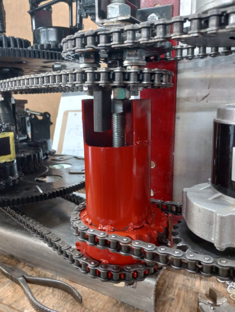
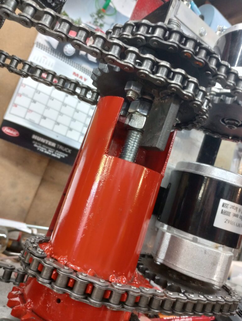
  9. Quantified Backlash Device (Drive or Coupler) = Coupling device with a specific calculated (quantified) amount of backlash, connected between rotating assemblies.
  10. Thornson Drive (EZKL) = A type-1 device which paved the way for modern Pulsed Inertial Engine technology.
  11. Reversion = The act of an object reversing its direction of movement or thrust.
  12. Wheel or Disc = The base rotating assembly currently being used to rotate the masses.

Quantified Backlash Drive Coupler

8/11/2024

Quantified Backlash Drive:

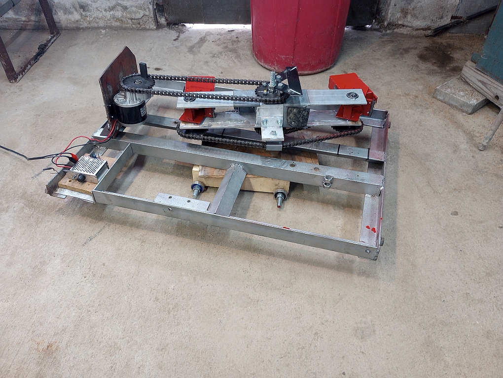
We have been testing the Quantified Backlash Drive (QBD) coupler for over a month now. Running the PIE 6.0 with 2 motors and the QBD keeping the synchronization within the working spec has resulted in a PIE that has minimal vibration, near constant thrust, reduced noise, low power usage, and excellent performance.

Actual thrust has not been measured, since this has been about the QBD design. The PIE 6.0 uses the rotating assemblies from the PIE 4 machine so thrust was never expected to exceed that of the PIE 4.

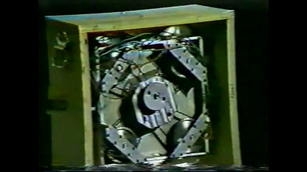
Thinking about the video presentation with Roy Thornson presenting his last design which was intended to go in an airplane to assist propulsion and even be the primary propulsive force eventually, we can see exactly why it never made it “off the ground”. In the video and in the very few photos available we can see there are 4 rotating wheels connected by roller chain, or timing belt, to a central motor drive hub.

Along with several other things that Roy never got figured out (to the best of our knowledge), Roy was unaware of the negative effect of reducing speed in the range of 90 degrees before the mass reaches “apex”. We reach this supposition because he did not use any kind of Speed Differential Control (SDC) system, so the rotating speed (RPM) input was constant. However, if there was a load introduced to the motor as it entered the 90-degree range it would be reasonable to think that the motor’s RPM might have dipped slightly. Even dropping a few rpm (example 150 down to 145) during that phase would be enough to cancel most of the propulsion!

Roy Thornson’s Prototype

IF Roy had timed the wheels all the same and used only 1 mass (weight) per wheel, it would work. He could have even spread it out amongst the wheels a bit to allow each to come to apex within a 20 to 30 degree range and still had some propulsion, but the only way to get that design to work is with a separate motor for each wheel, or pair of wheels, to attain a maximum of 4 pulses per revolution, AND, keep them synchronized (timed) with a QBD.

This said, it would now be possible to build a replica of his engine that, with the proper modifications, would actually work! — Any Takers? —

Successful Road Test

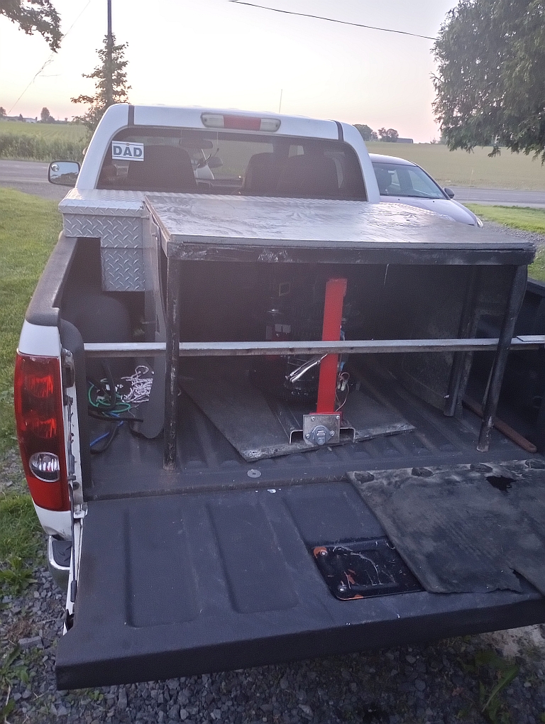
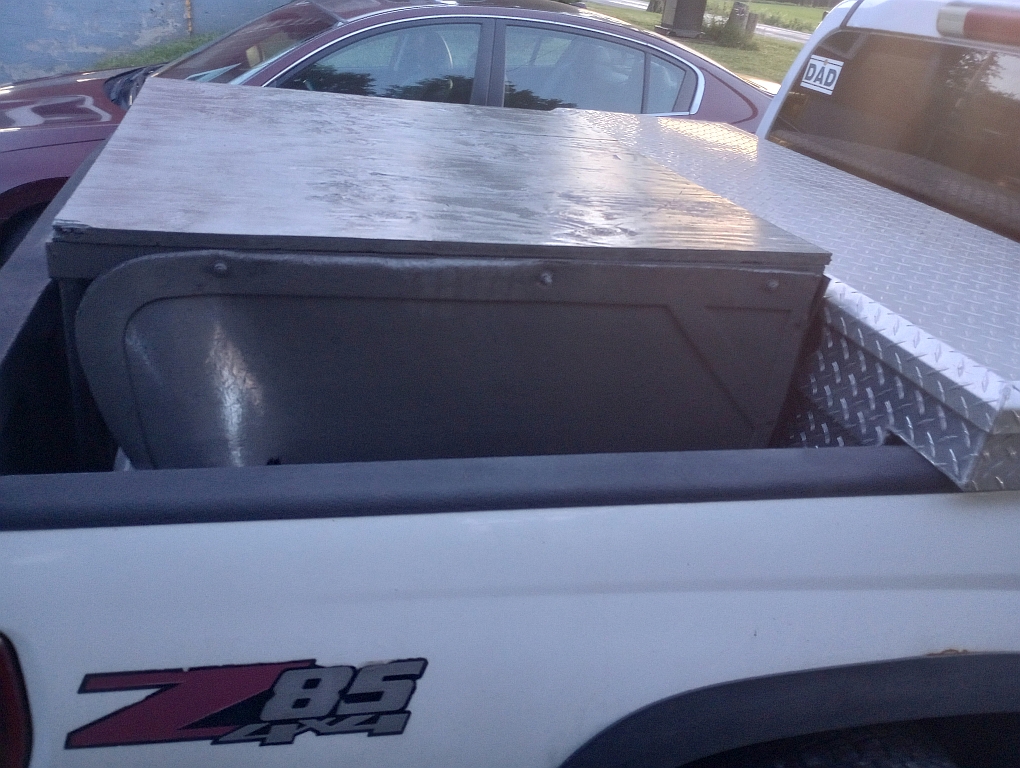
A few weeks ago (June 16, 2024), the PIE 6.0 was mounted in the test vehicle. A protective & sound deadening box made from steel tubing, plywood and several thick rubber mud flaps was built to cover it. Due to personal time constraints, it wasn’t run & tested until nearly 3 weeks later…

Getting The PIE 6 Mounted
Protective Cover (Doghouse

July 6, 2024: The PIE 6.0 has successfully completed its maiden voyage! The PIE design is solid so there are really no surprises there. This test was mostly about the Quantified Backlash Drive.

The PIE 6 is really two single-disc PIEs stacked on top of each other in a single framework. The two PIEs are timed 90 degrees apart to smooth the thrust pulses. Previously, this has proven problematic as the pulsing of one disc (or wheel) would detract from the pulse of the other disc when timed this way. The problem seemed to be that the rotational speed of one was directly affecting the rotational speed of the other. Also, the forward pulse of either disc was theorized to be affecting the building of energy in the other disc.

Two different design changes were proposed to test the validity of those 2 theories. The theory concerning rotational speeds seemed more realistic as rotational velocity manipulation is important to the efficacy of the design.

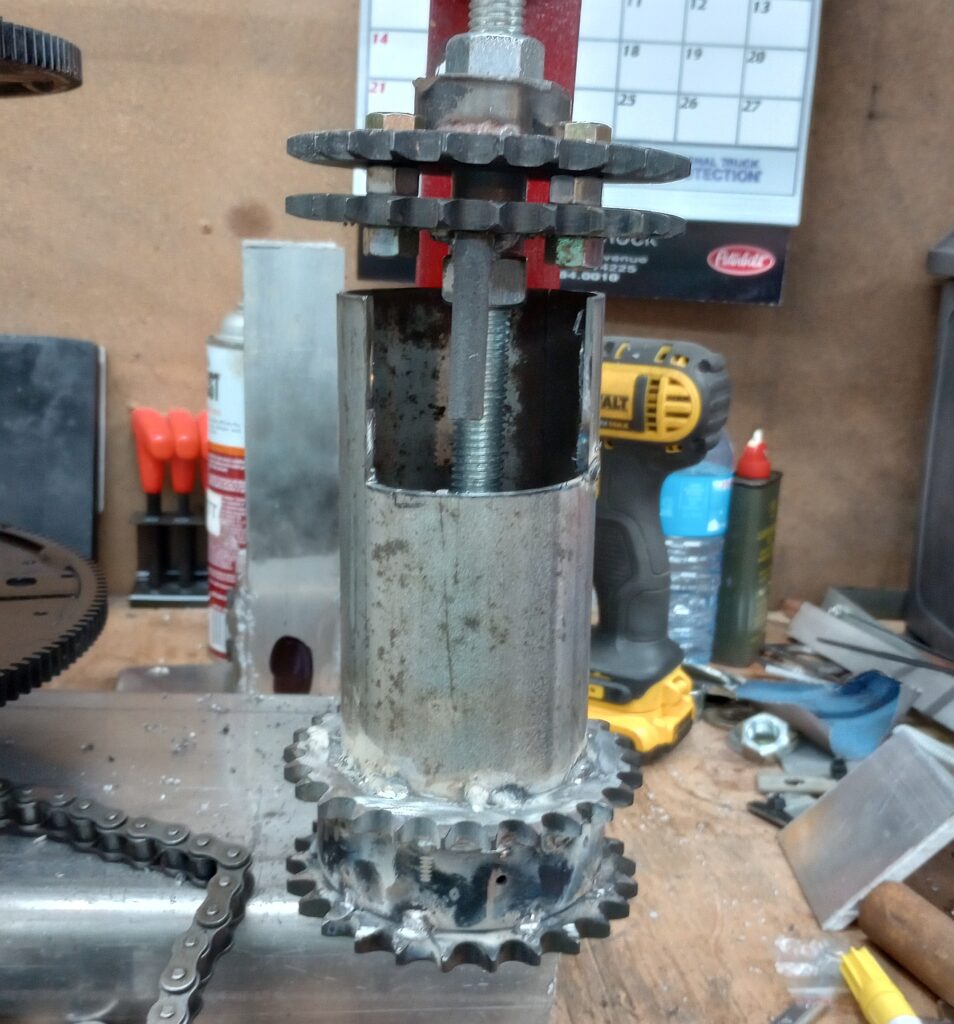
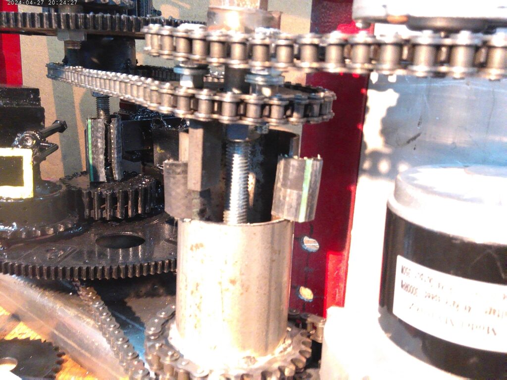
The Quantified Backlash Drive coupler (QBD coupler) allows the 2 PIEs to work somewhat independently, while keeping the initial 90 degree timing within an acceptable tolerance. This whole effort is only to smooth the pulsations of thrust without reducing the thrust of each rotating assembly.

QBD Coupler Being Assembled
QBD Coupler Being Set Up To Use

Proper testing of thrust on the test vehicle will now be conducted to satisfy the scientific requirements to validate the design. Even without proper thrust validation the QBD coupler’s success is allowing the PIE design to be enhanced for maximum power. Perhaps a pair of 30 inch rotating assemblies with 15 pound masses! Maybe not exactly, but you get the picture.

This is now making me wonder how many “failed” designs might have been successful if they had used multiple independent rotating assemblies tied together with something similar to the Quantified Backlash Drive… It should be making us all start seriously thinking about it!

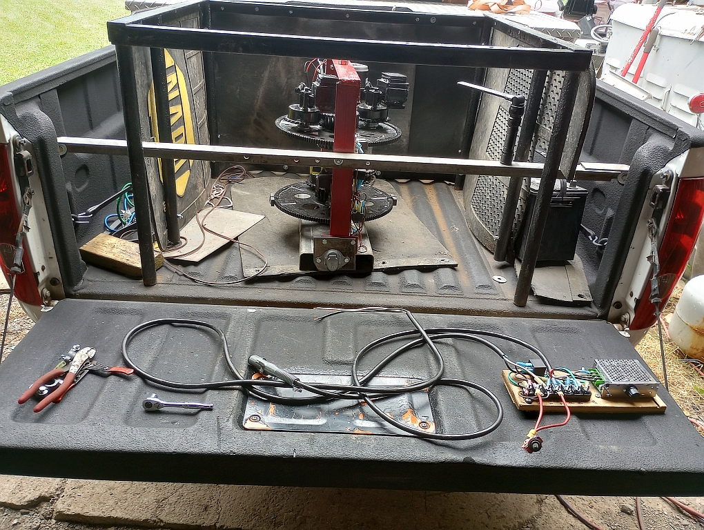
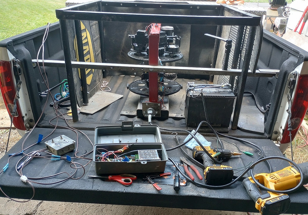
Setting Up The Control Box
Setting Up The Speed Controller
Ready To Test