Page 20, Prepping for Road Testing

May 9, 2020, Prepping for Road Testing

Preparations are under way to be ready and able to perform the next phase of operations, which is road testing. Since this will be tested in an open-air pick-up truck bed, several issues come to mind.
First, unattended operation. Nobody will be in the back with it due to state laws prohibiting riding in the back of a truck. If timing does slip, or there is a mechanical failure there will be a significant time lag between the failure point and human intervention. (Note: Most testing facilities also prohibit open-air riders without expensive safety harnesses and specialized equipment)
Second, the weather. The PIE needs to have some protection from inclement weather and from any debris that the wind could potentially deposit in the open gear mechanics of the PIE.
Third, nosy people. This is potentially the trickiest part of the testing. At this early stage of testing, a bit of privacy would be advantageous. The public is invited to view the data, pictures & videos online. Eventually there will be public demonstrations.
Preparations:

Secure vehicle mounting, with a weather resistant cover (hood).
Remote switching control, I prefer hard wiring for reliability.
Video monitoring, it would be good to keep an eye on the PIE if possible.
Graphic monitoring of engine load, done via vehicle computer interface.
PIE timing adjustments made & verified.
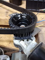
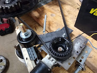
Tensioner spring tightened. Additional belt support may be necessary if there is a problem.

Note:

Moving the PIE & all its fixings back and forth numerous times, I can say that it most definitely wasn’t built with weight limitations in mind. That’s a polite way of saying that it’s freakin’ heavy.
I got out my digital AC scale & weighed the PIE, battery & axles just to get an Idea of the heft of the components.
Weight of the current PIE is 46.46 lbs., not including battery or rolling axles.
Weight of pair of axles used is 3.640 lbs., these won’t be needed for road testing.
Weight of battery used is 27.005 lbs., a battery is needed for “plug in hybrid” status.

Page 19, A New Video, Adjustments, & To-Do List

May 6, 2020, Adjustments Made, To Do List Update, & 3-Speed Running Video

Work has kept me busy with little time to spend lunch hours working with the PIE, but I did take the time to do some timing adjustments. It seems strange to me that the setting is so different between the opposing spin plates & the synchronous spin plates.
I have continued with timing adjustments being made for maximum thrust without the PIE on any wheels or rollers. It is reasonably easy to see torque & thrust when sitting on a bench or table since it will attempt to push the small bench in the forward direction, even to the point of tipping it up on two legs when thrusting.
Perhaps the final settings will (once found & recorded) will help enhance other designs such as the opposing spin design originated to work in a zero gravity & zero atmosphere environment, time will tell.
I did note that different timing settings were more effective at different rpm’s. When running on Low vs. High, the timing seems to affect efficiency from retarded to advanced and the PIE becomes much more sensitive to those adjustments at the higher rpm than it is at the lowest speed.
I also took the time to measure motor rpm working on all three speeds, with the photo tachometer. I know that values would be a bit higher if the battery was connected to a charging system, but at least this is a solid base value at an average of 12.2 volts.
Speed- Value- Source Volts:
Low- 36 RPM- 12.35v
Med- 53 RPM- 12.22v
High- 66 RPM- 12.10v
With the amount of thrust (yet to have a true measurement) generated in this speed range, I can only imagine what might be possible at a modestly higher speed of 100 to 200 rpm.
Once this is a successful working prototype, I have started putting together some drawings (on paper) to put both planetary sets on a single rotating assembly, thus reducing the sprawling layout and eliminating the need for a timing belt between rotating plate assemblies. I had better update the “To Do” list.
The updated “To Do” list:
1- A better locking mechanism for the sun gears to the axles.
2- A way to vary the sun gear timing by adjusting axle position.
3- A different drive system from the motor to the plates, maybe a double-sided timing belt or a roller chain drive.
4- Explore the possibility of having sun & planet gears on both sides of the plates.
5- Mount in a motor vehicle for road testing.

As seen on the list, although small side notes could be added to some of the listed items, I am very close to real world testing on a test track & ultimately the highway. 

Here is a video clip of the 3 different speeds. No timing changes were made during this run & on the highest speed, there is a significant leftward pull which will slide the front edge of the PIE sideways.

Page 18, Little Red Wagon & Modifications Made

April 30, 2020

I decided to put the whole unit on a small (rather wobbly) little red wagon to see if it would pull it around or at least if it would make it easier to push it up an incline. The wagon is far too wobbly to be used effectively but it did push it around my shop floor.

I also see the absolute necessity of making the sun gear timing adjustment lock securely. As I was testing, one of them suddenly drifted right, to the point where it tried to tip the red wagon over.

It was time to tear it down and rebuild the gear adjustment locks…And so I did…

Here is where I ended up.


I have realized that the only “good” video I have put here is of the first functional demo unit. Here is a video of the it with all of the latest modifications (listed below). I did not have it on wheels in this video, it is very difficult to keep it on the bench if there is anything under it that it will roll on.
 
Modifications Made:
Switched wires on motor to obtain an effective 3rd speed (I will measure that speed & post it here soon).
The center axles were removed for rework. 
Washers were welded to the topside of the lower beam.
The axles were repositioned downward to allow for double nutting underneath the beam.
The sun gears were welded to the washers (top side and bottom side), then were mounted back onto the axles where the washers were welded to the nuts & the nuts welded to the axles.
When mounting the axles on the beam, the bottom nuts are only somewhat tight.
A locking (double) nut added to each axle to keep the bottom nuts from loosening.
A pair of doubled nuts ware added above the center stop contact area, a metal top bar placed on them, and the axles are locked by tightening a nut on top of the top bar keeping the sun gears timed properly.
Settings:
Timing (T-belt) set at 12 & 1 o’clock.
Planetary weight set to contact center stop with plant gear approx. 40 degrees before BDC (Bottom Dead Center).
Running at highest speed allowed by the motor on a 12V battery.
Results:
On bench, no wheels, pulling bench violently to one side & lifting 1 leg of bench off the floor. 
Very encouraging!!

Ready for another test…

Page 17, T-belt Timing for Maximum Thrust

April 29, 2020 (T-belt Timing)

Now that the T-belt is installed & working with two flexplates, the question of how to time the two flexplates is at hand.
Since there is negligible backward push, it is all about “maximizing” and “smoothing” the forward thrust.

Observations made are as follows:
1- The closer the two flexplates are timed together, the forward push increases but so does the “pulsation” effect of the drive.
2- With the timing set at 180 degrees, the pulsation is very low but so is the forward thrust. 90 degrees does work, but I am not very pleased with the forward thrust & it almost seems that the two halves are fighting one another.
3- Setting the timing to approximately 30 degrees apart (12 & 1 o’clock positions) is very promising.
4- Although testing is necessary to state this conclusively, bringing the clock positioning closer together increases the thrust power more than a simple ratio would explain. If it were a “simple” ratio, clocked or timed at 180 degrees should produce ½ of the thrust but this does not seem to be the case. Since we are dealing with moving weights, rotating assemblies, and linear thrust, it would be logical to assume a formula must be used to calculate the thrust ad different timing positions.
I will be locking the positions of the stationary gears to their axles very soon to ensure the positions do not drift while running. 
That will be the very next step toward a road test!

Page 16, Timing Chain or Timing Belt?

April 28, 2020 (To Chain or To Belt, That Is The Question)

Since identifying the need to eliminate the belt-slip/speed-variation problem and because I want two flexplate assemblies synchronized and both turning CW, either a roller chain or a toothed belt has to be used.

The dilemma was in deciding which would be better.

I really like roller chains because they are a very forgiving utilitarian design which will work in the harshest conditions, even if not perfectly tight or aligned. The downside is that they are heavy, noisy & require regular lubrication.

I like toothed belts (t-belts) because they eliminate the downsides of a roller chain, i.e. they are light, quiet and do not require lubrication. The t-belt downside is that they are rather “finicky”, they need to be well aligned, tight and clean.

 After much consideration, I am installing a toothed timing belt for this prototype. If it proves to be too troublesome it will be replaced with roller chain & matching sprockets.

I have several used belts that were changed only for maintenance purposes and they have a rather common 8-M pitch, and I have some sprocket pullies for them, but the pullies would need extensive rework to fit my application. Because this is really a prototype, I decided to fabricate my own t-belt sprocket teeth on the existing flat pullies. This was pretty simple as the pulley circumference of 3” was almost perfect, & 1/8” rod is a nearly perfect fit to use as teeth for the sprockets.

I used a piece of timing belt as a guide and simply welded the teeth into place on each end.


Alignment of the pullies is a bit challenging, but it works pretty well.

With slightly out-of -round sprocket pullies & without a truly solid framework, there is deflection in the axles & motor mounting that causes the belt to slack off and snap back tight, so I installed a belt tensioner on the slack side of the belt between the motor & load.

The T-belt works well, and now the rotational speed is MUCH steadier. This has completely eliminated the belt slippage I experienced previously which was caused by the intermittent torque load.

I purposely started this T-belt testing with the flexplates in sync so that it would put excessive pulsing strain on the motor drive, and it has proven to be capable of handling the pulsing variations in load quite successfully.

The better it works, the more mechanical faults become evident, that is why this slow progression is absolutely necessary. If I started out with a reactionless drive unit that functioned perfectly, how would I ever understand all the things that make it work, and the things that will stop it from working?

#3 on the To-Do List… Done… But now an additional To-Do…

The updated “To Do” list:
1- A better locking mechanism for the sun gears to the axles.
2- A way to vary the sun gear timing by adjusting axle position.
3- A different drive system from the motor to the plates, maybe a double-sided timing belt or a roller chain drive.
4- Explore the possibility of having sun & planet gears on both sides of the plates.
5- Mount in a motor vehicle for road testing.
6- Change synchronization of CW turning plates to reduce pulsation.

Here is a first test run video with the motor running on low speed and the unit not being allowed to move.


Page 15, Stability vs. Instability & Revised “To Do” List

April 21, 2020
The working phrase of the day is: “There is a necessary dynamic stability in the build as well as a necessary dynamic instability. An Excess of either is intolerable”.

I learned a few things today. Some of these things I already knew, but was not giving proper consideration, others that have formed new ideas and will be added to my list of things needing exploration.
Today I made it into a 3-wheeler, two flexplates turning clockwise (CW) & one turning counterclockwise (CCW). The two CW plates are timed exactly together while the CCW is still 90 degrees behind them. The amount of forward push effectively doubled, coming from the pair of CW plates. And the single CCW quite effectively extends the time that the machine pushes between “pauses”. This tells me that configuration is of the upmost importance!
I learned quite a bit about this machine’s timing & it seems that it can be correlated to a spark ignition type IC engine’s timing (cam, tach, dwell & timing correlation).  
The obvious list is as follows.
           Inertial Drive:                           IC Engine:          (Definition):
           Flexplate timing                     Camshaft Timing   (Timing gears, chain or belt)                               
           Planet Timing                         Ignition Timing      (Distributor timing)                  
           Inner Stop to Outer Stop       Ignition Dwell       (Ignition coil saturation time)                
           RPMs                                   RPMs                  (Speed of rotation)    


I also had an issue with the belt slipping. At first I didn’t notice the slippage, but there was suddenly a problem with the drive oscillating back and forth. Tightening the belt corrected this oscillation.

This has led me to the tentative conclusion that dynamic rotation speed is very important during the time when the weight is between the inner & outer stops. 

I cannot help but wonder if changing motor speed at precise times could enhance the functionality… The velocity of the weight is already being manipulated by the orbital path, why not expand on this premise.
I believe that the intermittently slipping belt (caused by weak motor mounting) was what would intermittently cause poor performance. I also believe that it could be an important discovery! A feature that could be added as a performance enhancer if the timing of speed differences were reversed!
The updated “To Do” list:
1- A better locking mechanism for the sun gears to the axles.
2- A way to vary the sun gear timing by adjusting axle position.
3- A different drive system from the motor to the plates, maybe a double-sided timing belt or a roller chain drive.
4- Explore the possibility of having sun & planet gears on both sides of the plates.
5- Mount in a motor vehicle for road testing.

Page 14, Phase 2 – Outer Stops Cont…

April 14, 2020


The revised outer stop (os2) seems to be the most effective, however, it should be noted that it also puts the heaviest strain on the gears. The strain tends to change the timing of the sun gear(s). I am thinking that I should fasten the sun gear(s) to the axle shafts and change the axle shaft mountings to enable “on the fly” timing adjustments.
I have also added the stop tab (which contacts os2) to one of the 1” square weights. The result was a dramatic improvement over the original trials with that weight and I also had to add an extra stop tab to the 1” square to keep it from “backfiring” or spinning itself around to the wrong side of os2.
This all showed me that the os2 is really absorbing a tremendous amount of torque from the weight, and as the timing of the sun, planet and weight are becoming much more critical it is also having a harder time maintaining adjustment.
Note: After multiple, successful tests the forward thrust would suddenly be very diminished. Sometimes it would seem like the whole thing had been a joke on me & I would get very discouraged. 
This has been found to be the effect of the timing slowly slipping while test running. This illustrates the need for an improved locking mechanism for the sun gears, with an allowance for adjustment as needed.
 

Page 13, Phase 2 – Outer Stop

April 8, 2020

The outer weight stop is the device that stops the outer weight from swinging past the apex position of the planet gear. It stops the swing, absorbing the energy being imparted by the inertia of the weight, transferring that energy into forward motion and allowing the weight to stay at apex until it returns to the center of the sun gear and contacts the inner stop. The inner stop holds the weight until it is in position to be swung outward/forward where it contacts the outer stop again.
This illustrates how important the stops are and it begins to illustrate the stress imparted upon the gear teeth and the locks that keep the sun gears timed properly.
The outer stop seems to be where a large part of the stress is, so that is where I am concentrating my refinement efforts.
I have now tried several stops, and the 2 most successful will be called os1 and os2. Os1 is fastened directly to the planet gear and extends outward toward the weight where id stops the swing by contacting the weight’s connecting rod. Os2 is fastened to the planet gear but is inboard of the weight’s pivot. Os2 requires an extension coming from the inboard side of the weight’s pivot which contacts the stop. Intuitively, this seems to be a better idea. We shall see.

April 9, 2020

The outer stop version 2 (os2) seems to be much improved over os1 and I have changed 2 planet gears to utilize this improved design.

One of the (hopefully) benefits of this design is a change in the timing which directs much more of the generated force toward the forward direction. So much so, that I “might” be able to eliminate the counter rotating assembly. If I can, this will greatly improve efficiency!! I am hopeful.


Page 12, Phase 2, Refinement of the Drive & “Successful Failures”

April 7, 2020


The refining of this drive system requires intimate knowledge of what does NOT work! There have been many tries & fails throughout multiple projects on my path to this point.
It is very difficult to remain optimistic through multiple obstacles, many times where I would have to avoid the deep, sucking hole of self-doubt & even depression.
 Every time something that I thought should work, but didn’t, I HAD to see it as a “Successful Failure”. That means there is no such thing as a failure, only the opportunity to learn. That is something which made me a great diagnostician in the auto repair industry for so many years (or, so I am told).
Fortunately, that makes the successful tests, changes & experiments that much more gratifying.
Now begins the refinement of this reactionless drive into a final product that can be a useful addition to mankind’s goals of energy independence as well as cheap & efficient propulsion for virtually all types of transportation.
This refinement now begins:
The components that need immediate work are twofold, first is the “stop” taking the place of the outer planet trap & second is accurately controlling the timing of the planetary gears.
First will be the stop. I am presently working to increase the efficiency of the pendulum weight stop and hopefully impart the weight’s force more effectively.