Hello Everyone,
Sorry, no photos in this post…
June, 2023. What a crazy last few years this has been and 2023 is no exception! When I started building inertial propulsion devices, it was approximately 20 years ago. Those initial devices failed miserably because I did not understand the principles I was looking for. At that time I was working with energy converters and at that time I just wasn’t thinking about propulsion as moving of energy I was thinking about it as moving of mass. I couldn’t have been more wrong! So now that I do understand these things, and as I came to a fairly clear understanding of these things in the late 2010s, it brings us to where we are today!
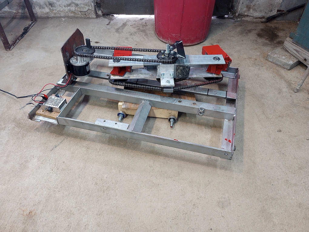
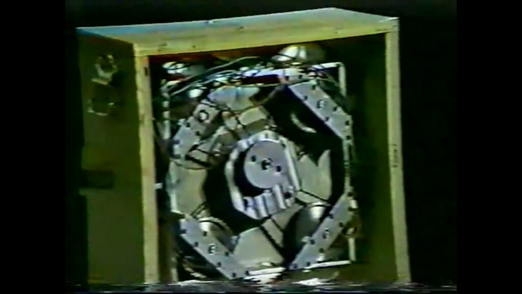
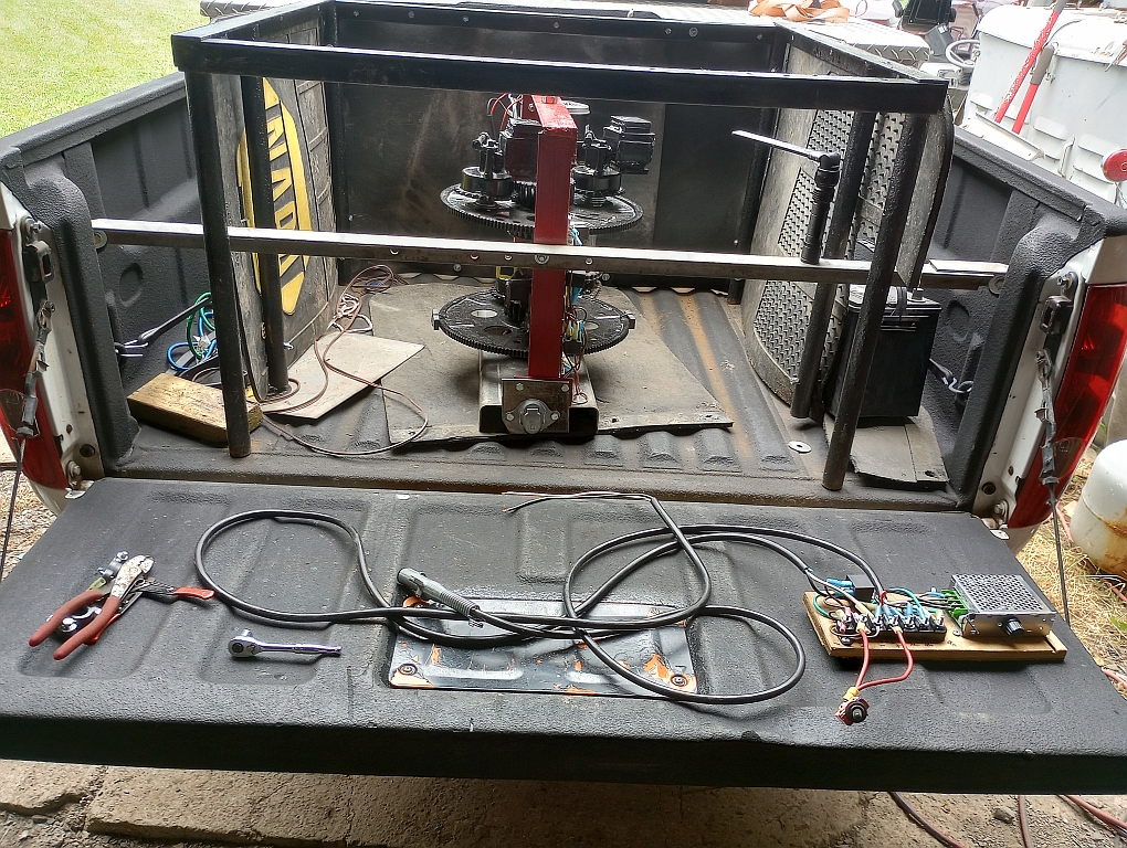
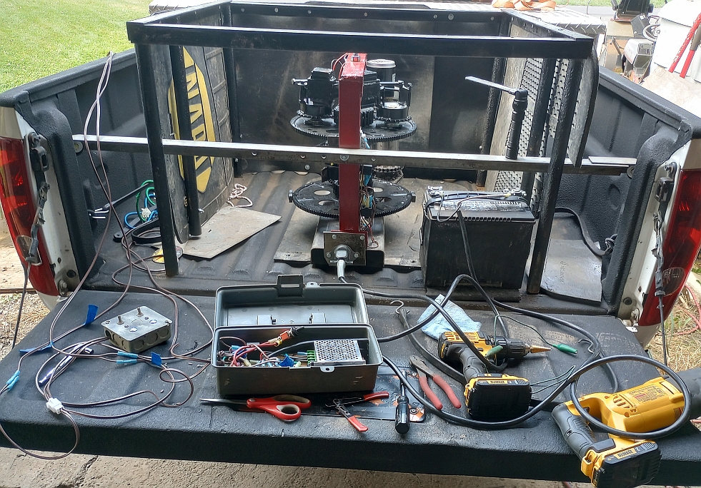
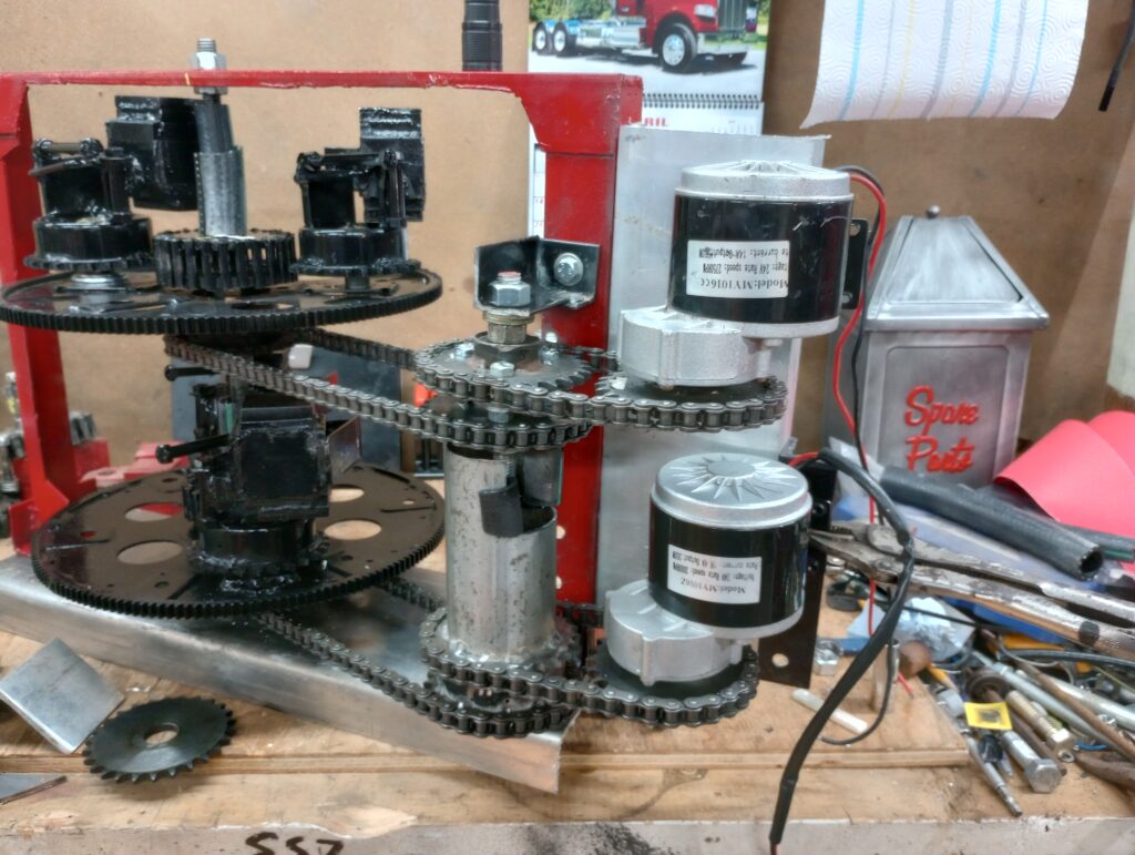
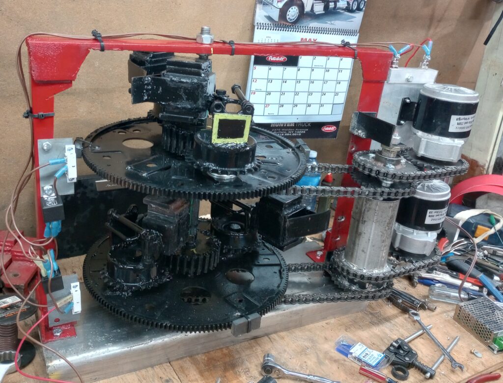
So the first of this year, 2023, on New Year’s Day, we had the very first ever successful duplicatable test of the Trammell engine! We had had some successes before, but I don’t call those true successes because they were not duplicatable. On January 1st I could stop the machine, start the machine, rev the machine up, slow the machine down and watch the same exact reaction with every single change that I made. That is what I call success! So since then the travel engine has undergone a couple of changes. We’ve gotten better at backfire control, we have a much much stronger engine that is the electric motor, and we can duplicate on demand the fact that it produces thrust. This thrust is in the upward direction it is and it is hanging from a balance beam type scale. Thrust begins while hanging in me there not sitting on a table top or floor to make sure that we are not pushing off against something. As the machine comes to speed it’s thrust is actually the strongest and then tapers off just a bit I suppose if the vessel had several of these travel engines it could start and stop them in sequence creating large quantities of thrust in short duration pulses.
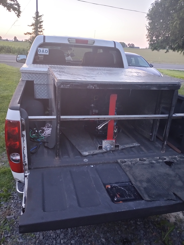
The biggest problem with the travel engine right now is that I built the damn thing so heavy that it is difficult to move around, and there is no way in the world it would ever be able to lift itself. Currently it weighs somewhere around 320 lb. So not wanting to destroy what actually does work now it is time to duplicate it. Science tells us if something cannot be duplicated it’s reasonably worthless, so V2 has been started, that is Trammell B2.
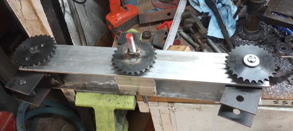
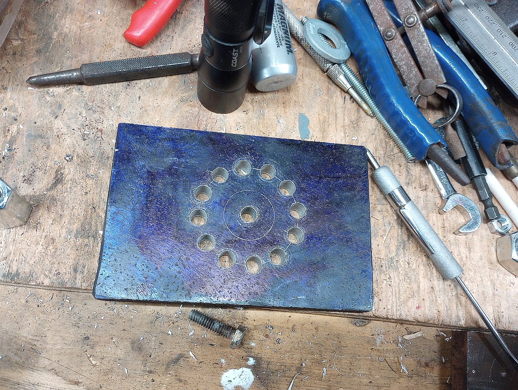
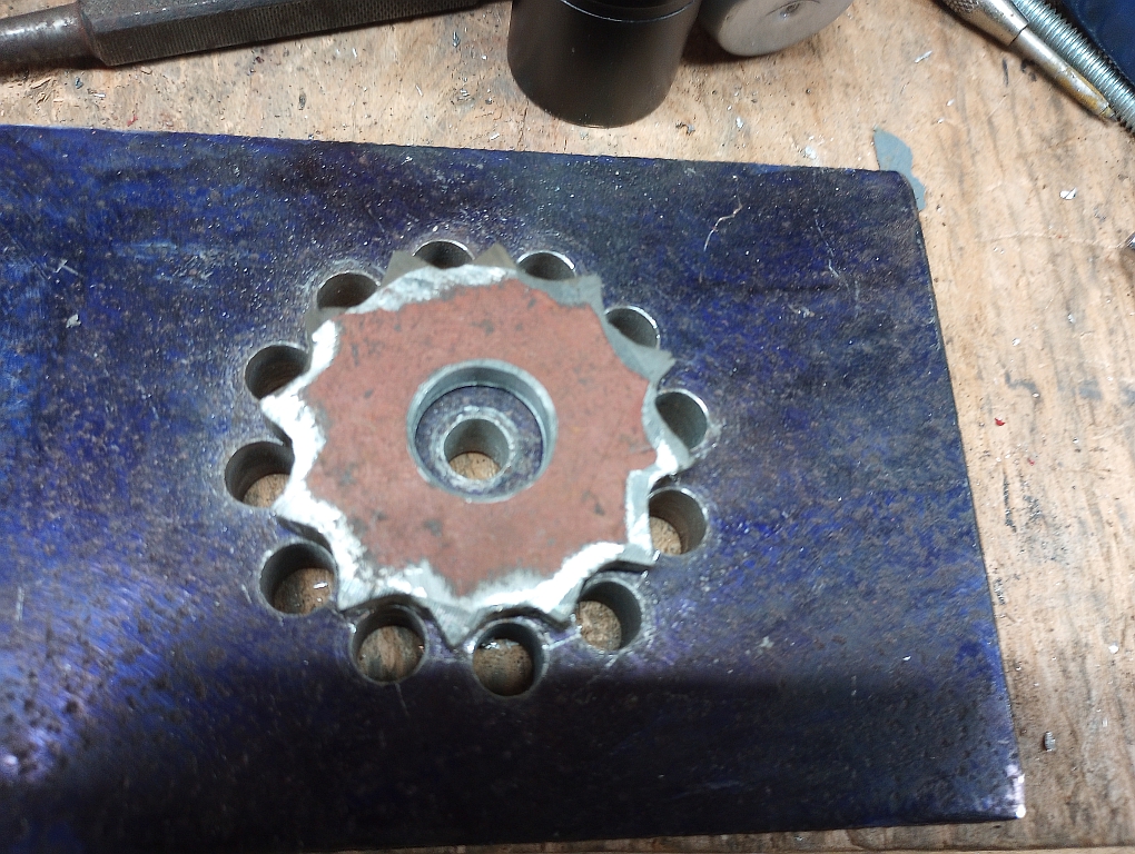
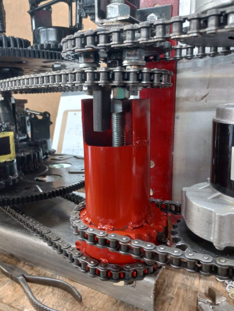
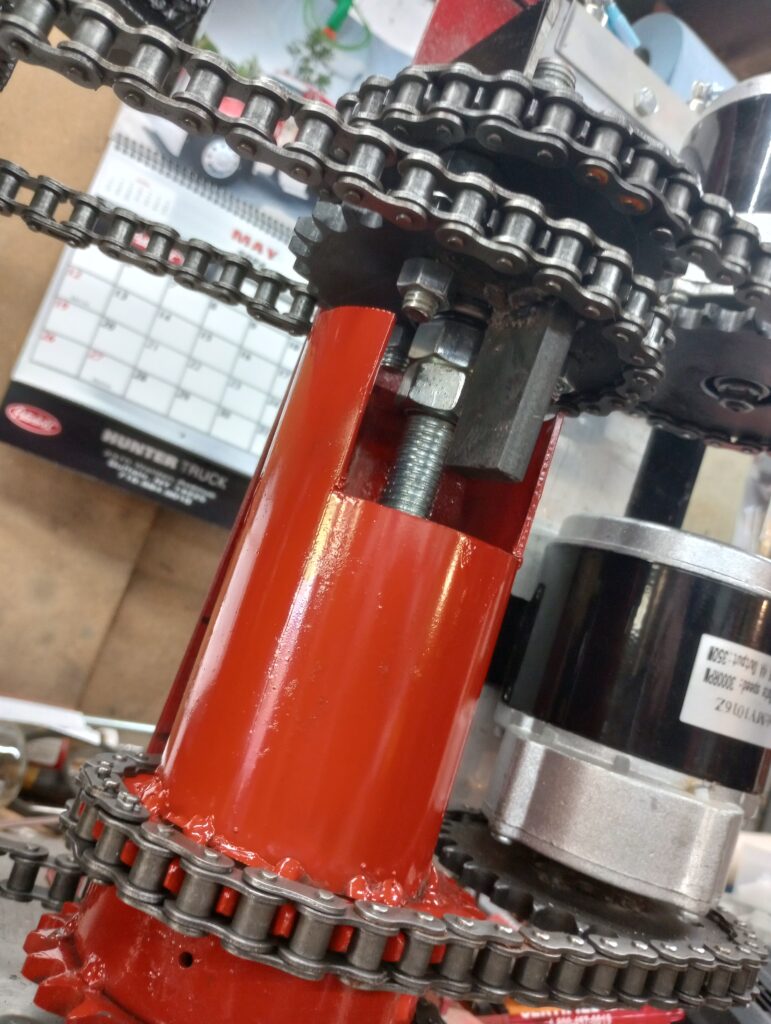
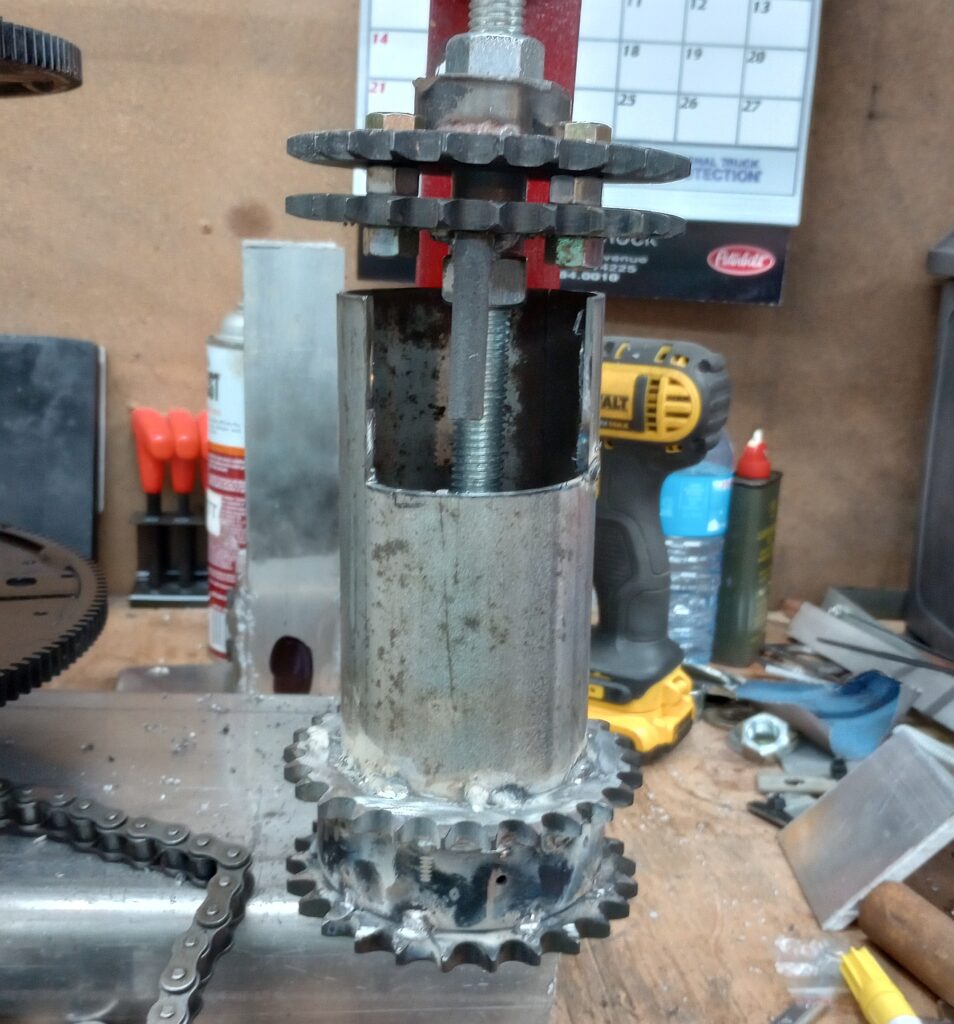
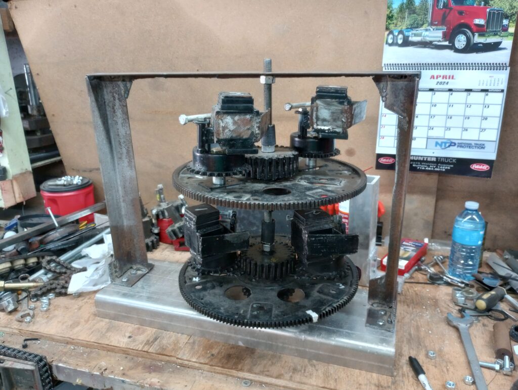
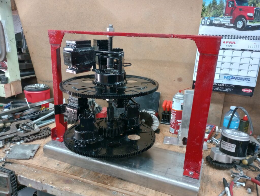
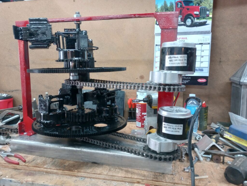
This new version of Trammell is seeing the framework change shape just a little bit. It is no longer going to be a box design, it is also not going to be heavy steel parts making up the frame. The hubs are also going to change, they are not going to be automotive bearings, and even the discs are changing quite a bit as The originals were half inch thick steel, and these are 3/8 thick aluminum plates. I am shooting for under 50 lb for the entire machine, although I don’t know what motor I’m going to use yet so that is going to determine the final weight.
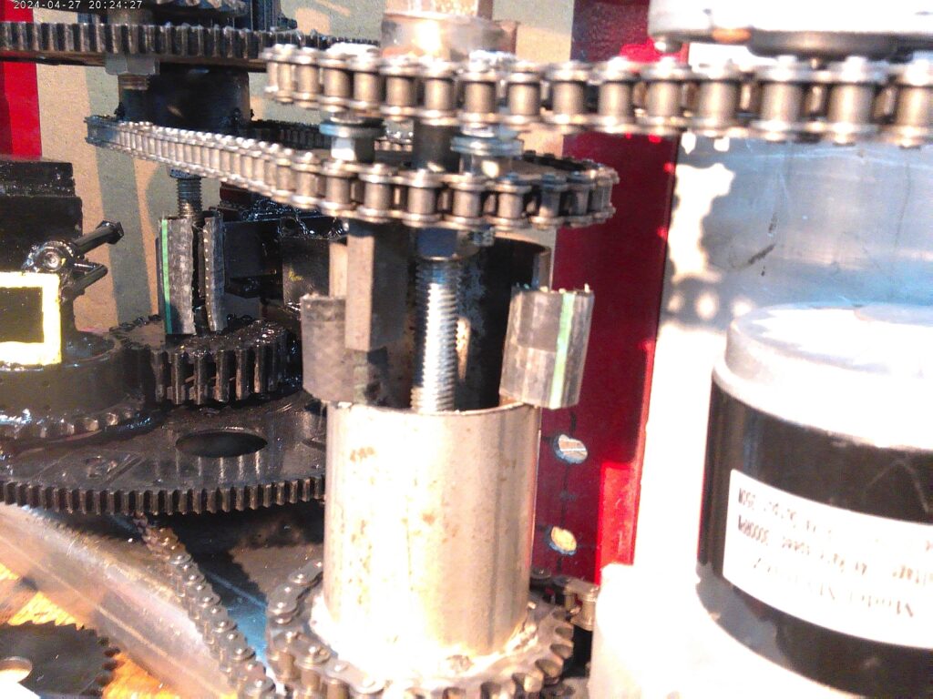
So a little bit about how the Trammel works, although currently we are not giving away all of the secrets. If one was to think about a fisherman sitting on a dock or better yet in a boat, and he had a fishing rod with a 1 lb weight at the end instead of bait to catch a fish, and if that one pound weight was able to be pulled back and thrown out quickly and effectively, one could imagine the fisherman in his boat casting that weight out into the water but before it sinks into the water he jerks on it really really hard and pulls it back into the boat just as quickly as it was cast out. The act of casting it out took much more time than the act of jerking it to a stop and starting its pull back. That time differential along with the hard jerk versus the nice slow smooth cast is exactly how a mass displacement machine works. The mass is actually attached in one component where it is removed temporarily attached to a second component which is already moving at speed, and then that second component brings the mass to a stop and reverses its direction brings it back to full speed and then hands it back off to its first component. That first component brings it back around to where it’s going to meet the place where it will disconnect from that component and be transferred to the second component again. It will do this thousands and thousands of times! If the electric motor input is running at 1000 rpms, it will do this transfer in two different places within the machine twice her RPM making 2,000 actual pulses but 4,000 actual transfers every minute. This is why the faster the machine runs, the more power it produces! Hopefully soon we will have new models coming out which will be tested out in the real world on real vehicles. Either wheel vehicles, floating vehicles or even flying vehicles! I don’t see us taking this to space right away since I don’t currently have a ride, but as the tech develops it just might take itself there!
I am not going to just “give away” the secrets before we have a chance to properly develop the Trammel technology but in the upcoming series of posts, pictures and videos, the principles of operation will be discussed. Perhaps a series of YouTube videos as well…
The upcoming series will be, “The Trammel Engine”.
That’s it for now, thanks for sticking with me through this crazy journey and waiting so long between posts. Please be good to each other and have a great day…
